
Air Boxes & Filters (1)
Question:
Could you give me some advice about the change in power characteristics after installing an airbox. The result – Top speed slight increased but slight decreased torque at slow and middle rev than before (used open air filter with long air horns). Now changed short air horns, I hope to get a top speed and useful torque at low rev. When I installed an airbox, I thought to get ram effect and more power.
Answer:
Shorter air horns will normally reduce the lower to mid range torque, but potentially increase upper bhp, this is provided that the air horn length is optimised for the engine in the first place for all round characteristics.
An air box can have a dramatic effect on performance. Unfortunately this effect can vary from installation to installation e.g. a change in cam design, compression ratio, air horn length can sometimes have a negative effect and sometimes even a positive effect. The only way to discover what is best is to try every combination possible.
To prove ram effect this can only be done either in a pressurised dyno cell and then measuring the air pressure inside the air box when the car is travelling at speeds. The ECU will also have to be able to compensate for changes in air pressure within the air box. Sometimes you may actually find that the engine itself when driven at speed had negative pressure producing loss in performance, but once the air box is fitted you were able to maintain atmospheric pressure which means that you have a net gain as opposed to gaining positive pressure and a gain over what you would see on a rolling road in a static condition.
Category:
Air Boxes & Filters
Alternators (1)
We offer 2 sizes of alternator 50amp & 95amp, as far as your choice of output is concerned, ideally you need to know the current drain of everything that you have fitted e.g some vehicles nowadays have electric power steering, even heated front and rear screens and a huge array of spotlights.
If you have spot lights, many modern LED spot lights have a relatively low current drain in comparison with older HID systems, the larger 95amp version will give you more capacity.
Remember the alternator can charge your battery quicker with a larger output, it just gives you that extra comfort and piece of mind.
Category:
Alternators
CAN Based ECUs (2)
Question :
Is it possible to configure your own CAN bus messages to be sent out on the CAN interface on the MBE 9A9 ECU? Is it capable of receiving CAN messages and acting on them?
Answer :
The CAN Bus data stream is designed for use to transmit data to either external devices, such as data loggers or data to other MBE systems. It would be possible to control other devices that are CAN Bus controlled.
For example, if you have a gearbox that has a CAN Bus system on it, it can indeed control it. The problem you have is that the manufacturer of the gearbox is unlikely to release the protocols required to control the gearbox and the same would go for any other systems fitted to production cars. If you are able to get the protocols, the software could then be written to control them with the MBE CAN data stream and depending on how complex the system, would depend on how much time was required for the software engineer to write it. This may only be a matter of a couple of days of work, which would then need to be charged to the customer requesting it.
Unfortunately, if the data stream information is not available from the manufacturer, it would be virtually impossible to write controlling software to control the CAN Bus of each product, since you have no idea of what the information requires to control it. It is like looking for a needle in a hundred haystacks. It is potentially months of work just trying to decode what is required and the cost would be far too expensive.
Categories:
CAN Based ECUs,
MBE Management Systems
Question :
I have Ford Fiesta Mk7 power steering unit (TRW Column Drive EPS CAN control) and I would like to use it on my Fiesta Mk2 Duratec HE 2.0 Racecar. Can any MBE ECU control this unit?
Answer :
The only problem you are going to have is getting the CAN protocols, no manufacturers release their CAN protocols. In the past, MBE have done development work for large manufacturers themselves and even then they would not release protocols outside.
The problem with anything that is CAN controlled, is that you have no idea what the messages should be and even if you discover some messages that get a system working, there may be other hidden safety messages that are being used to check that the system is working correctly. If these messages are either not received or transmitted, the system may appear to work correctly for a short period of time and then simply switch off assuming there is a fault. Hunting for any CAN data messages is like looking for a needle in 100 haystacks, so without the original CAN datastream protocols, it would be cheaper to fit a completely different system.
Obviously in the event of you being lucky enough to get the information required, if you are running an MBE ECU to control the engine then some protocols could be written to do the job required. We also need to know what other functions are necessarily associated with it, to decide which would be a suitable ECU for your needs.
Category:
CAN Based ECUs
Duratec Specific (3)
Question:
Can a Ford head be bolted straight onto a Mazda?
Answer:
Although the Mazda and Ford engine are fairly similar, Mazda do change quite a few components and it is difficult to get an idea of what they do and don’t change on various models. The cylinder head itself should bolt straight on, but you would want the chain guides, sprockets and drive gears from the Ford engine. At the same time, you can fit the keyed components as listed on our website for reliability. I do know that on the 2.0L version, that the Ford crankshaft was much stronger than the Mazda one and Mazda had to change their crankshaft to a much higher specification for reliability.
Category:
Duratec Specific
Question:
Hi, I’m having trouble with Duratec cooling system. The car is RWD Mk6 Escort and the rad is mounted low hence the rad top hose has to dip down. The water rail has no rear outlet to run heater or bypass hoses just has a switch to operate rad fan. The Mk 6 has a header tank with a air bleed to top of rad. Runs and cools perfect until sitting at idle when it starts to heat up. Do I require a extra bleed pipe from top of rail engine or bypass and heater pipes refitted. Or do I put on a David Craig pump, any thoughts would be greatly appreciated.
Answer:
All our vehicles are equipped with an electric water pump controlled by our ECUs. We do not use the mechanical water pump due to shortcomings in the Ford design. If you are using a mechanical water pump, great care must be taken and bleeds are always essential to prevent air locks. We have no diagrams for the mechanical system as this is not something we recommend. The diagram on our website is only for the electric water pump design.
Category:
Duratec Specific
Question:
Do you have a piston for a 2.0L Duratec with a 89mm bore?
Answer:
We only manufacture two piston sizes for the 2.0/2.3L Duratec. We produce either 87.50mm to replace the standard piston in a standard bore or 88.00mm piston so the bore can be cleaned + 0.50mm oversize. The reason we do this is because the standard liner, which is cast into the Duratec block has been specially developed by Mazda/Ford. We have looked quite closely at replacing this liner because we get regular requests for bigger bore sizes, there are several problems;
1 – The liner is very thin, which allows it to expand and contract with the aluminium that is cast around it.
2 – The modern Duratec engine has not been designed to be rebored at any time in it’s life, therefore the thickness of this liner is calculated to be correct at the 87.50mm bore.
3 – We made a decision due to the design of the liner to allow only the smallest of rebore sizes to rectify a small amount of damage to the liner itself, this was the reason why we picked 88.00mm.
4 – If we were to increase the bore size greater than 88mm, the liner thickness would become too thin, in our opinion, and over time would begin to distort.
5 – Many of our competitors have not, in our opinion, taken this into account and although your engine may run successfully for a short period of time depending on use, eventually problems will occur creating premature engine wear and eventually failure.
6 – Several companies have been replacing the liners, when the original liner is replaced there are several issues; the thin construct and ridged shape means that a lot of material has to be machined out to remove the original liner. This then means the aluminium left, particularly between the liners is very thin. The liner that is then used has to be off a completely different construction as it needs to be more self supporting, which is fine as far as the liner is concerned but the issue that arises is the thin layers of aluminium that expand and contract around the new more rigid liner are too thin and expand at a different rate to the now more rigid liner so again initially the engine will run ok, but the feedback we get from customers who have tried this option find failure seems to always occur in the short term in high performance engines but this takes a little longer on a road based engine.
Although there may be a way of overcome the issues with replacing the liners, I believe the only way to do this successfully is to redesign the interior of the block completely, but this would be a very costly exercise and therefore should only be undertaken on turbo engines over 500bhp. It would actually be cheaper to replace the complete engine than it would be to carry this kind of work even when once developed properly.
So my suggestion would be to go with either the stock or +0.50mm version and if you are engine has more damage than that, that the block is replaced.
Category:
Duratec Specific
Easimap Software (9)
Question :
How do I make a back up on chipfile in my ECU?
Answer :
Simple instructions for making a backup:
1. Power up the ECU, plug in your mapping lead (which must be a proper mapping lead, NOT an RS232 extension lead).
2. Open Easimap 5 programme, this should then identify your ECU and set a real-time view automatically.
3. Select ‘chipfile’ from the drop-down transfer chip data, provided your ECU is powered up ‘ECU’ will be highlighted in dark blue. The words above this in the grey section will be ‘select source device’. Hit the ENTER key, (do not use mouse keys as you can easily double click and send the information back from where you got it).
4. You will then get a screen appears again with ‘select Target device’. With the use of the up and down arrow, highlight ‘other chip file’, hit the ENTER key, you will then have a box appear as ‘save as’ and the file name will have a flashing bar. You must then enter the name you wish to give it e.g. Chris Platt 1. Then hit the SAVE button.
5. The map will then be slowly transferred from the ECU to your laptop. This may take a minute or so.
If this does not work, you would need to reinstall Easimap 5.
Category:
Easimap Software
Question:
Could you please confirm which input pin would be desired for a pull up or pull down 5v digital signal.
Answer:
The easiest way to confirm which pin is suitable is simply to plug into the ECU with the MBE985 USB/CAN interface (basic mapping equipment MBE-MAP-KIT-3-CAN). Easimap 6 will then automatically select the correct .ec2 file to match the software as the ECU you are proposing to set up gearbox control with. You will then be able to go to programmable pins and look at the drop down option for each of the pins and see if this option is available.
Because software is continually updated and changing, new functions and options will become available over time and there is always a possibility that the software version that your ECU has different functions available and therefore this can only be confirmed by plugging into the ECU or having a copy of the map from the ECU along with knowing the software version the ECU is currently using.
This applies to all our MBE ECUs
Categories:
Easimap Software,
MBE Management Systems
Question:
What is the relationship between Current Faults and Logged Faults in Easimap 6. Presumably a fault will disappear from Current Faults as soon as the condition is resolved, but does it then remain in Logged Faults? How long do they remain in Logged Faults for? And is there a way to clear or reset the Logged Faults?
Answer:
The 9A* range of ECUs has the option to display current faults and logged faults. The current faults will only exist while it actually has that fault and then the status will return to being ok. The logged fault will only log the fault until the ECU power has been cycled.
This way if you wish to diagnose a fault and the fault is intermittent, you may miss it in the current faults section, but it would be obvious in the logged fault provided you do not cycle the ECU power.
Categories:
Easimap Software,
MBE Management Systems
Question :
I would like to make some alterations to the standard map to improve cold starting (the car struggles to idle when cold). However, I’ve just realised that my laptop (being fairly current) doesn’t have a serial port. Is it possible to connect the ECU to a USB port (and if so can you supply the Farnell parts list) or do you know if the regular serial coiled leads that you supply can be used with a USB to serial adapter?
Answer :
If your laptop is not equipped with a serial port you will need to purchase an adaptor with the appropriate software from a computer supplier. This will allow you to convert your USB port to run serial.
Once you have downloaded the software & have everything talking correctly, your ECU will almost certainly ask you for a PIN code, all our ECUs are coded with 1111. I would suggest before you attempt to make any adjustments that you look at the device info, as the throttle bodies & fuel pressure must be correctly set and the settings for this are written within this section.
Most importantly of all, is before you make any adjustments make a copy of the maps stored in the Ecu. This way if you make any mistakes you can restore your original map, if you lose your original copy we would have to make a charge to replace it. You should find sufficient information within the help file to carry out any modifications you think necessary & you should familiarise yourself with the system before attempting any changes.
Category:
Easimap Software
Question :
How do we modify the fuel map? How do we send the modified map to the ECU and have the ECU run that map? How do we know the ECU is actually using the map we have modified? We are trying to do this statically before we run the engine because the map that is currently in the engine if far too lean. Unfortunately when I play with the maps and settings and click on the panels in the system, the information about how to save the data, and how to send that data appears to be missing. I have installed a lot of software in my life, and have taught myself how to use a lot of software, so I’m fairly intuitive about learning the software. I am not used to having instructions in the help manuals tell me to do something and then finding that the software doesn’t have the commands to follow the instructions. It’s a bit frustrating, to say the least.
Answer :
Any ECUs we send out directly to our customers come fully programmed and ready to use, there is information within the device info which normally helps with the set up of the engine. Easimap 6 has all the icons that are normally required across the top of the software, as you pass your mouse across the icon it describes what each function does. Because the software is continually evolving on almost a daily basis, it is impossible to make the help file anything more than a basic guide as improvements are added to the software itself, the information is added to the .ec2 file next to each new function added.
If you can give us more information as far as an invoice number when the ECU was purchased and any relevant information will help us to help you. We try to give as much help as possible to our customers but unfortunately with the many thousand of ECUs that we sell every year, it is impossible to have engineers available to give detailed free support as the cost of the initial ECU is literally the price of the ECU itself.
When you install Easimap 6 from our website, it should install correctly. We have occasionally seen some firewalls block part of the installation and therefore not all files are installed correctly. You could reinstall Easimap 6 as many times as you wish without any problems. When first downloaded, it is in its basic form and this is for the beginner so as to make things as easy as possible. This should normally be all that is required for any ECUs that we have programmed since the most that should normally be needed is to set the throttle pot. If the engine has been tuned, then access to the fuel and ignition maps would be needed but this is available even in the basic access. As you become more skilled you can access the advanced level by clicking on the profile at the bottom of the screen and then Master level has a password which is only normally required by accessing more complex functions, not normally associated with the running of the engine.
Once you give us further information as far as the ECU software is concerned, which will appear at the top of the screen in the panel marked ‘no device’ when the ECU is not connected. Easimap 6 will identify the ECU software and then automatically load the closest matching .ec2 file (for example if your ECU id is #9A4bd600, the .ec2 file it will load will be 9A4bd60a [could be anything from a to z depending on release]), which will then appear in the box to the left. If no ECU is connected, it will remember the last .ec2 file that was loaded by Easimap 6 which may not match the ECU you have connected. Once the ECU is connected If you confirm this software version, if it is later than the version on the website, we will email you a zipped copy for you to install into Easimap 6.
Category:
Easimap Software
Question :
I made changes across several maps and then chose “Transfer All Data”. The transfer seemed to work successfully, but now it appears that the reverse voltage TPS curve for this Cosworth engine has been lost. Prior to making the changes, TPS was at site 5.1 at idle. Now, it is showing site 14.9 at idle, and voltage sweeps *downward*. It appears that something was lost when I transferred all of the maps. I did *not* change the throttle index map.
Answer :
You say you used “Transfer All Data” this tool allows you to move a chip file from one place to another, my guess is that instead of taking a copy from the ECU. You have taken a map from somewhere else and loaded it into the ECU. This means that you have not only loaded a different TPS index map but its setup as well and the rest of the map may also be different.
Hopefully, you made a copy of the map you had been working on previously and you can now reload that. If not I have attached a copy of the map loaded into the ECU when it was first sent to you. Use the 2 Chip Icons on the top left of your screen to save a copy of data in the ECU and send the new map if you need to that I have sent to you.
When mapping an engine I always make a copy of what is in the ECU and then make a copy of that to save changes to at the same time as to make changes to the ECU( use the send but on top of each map to send to map and then ECU). I can then compare changes made with the “ Compare Device Data” to see is I have missed anything or made a mistake. I can then fix or reload earlier maps if needed. I will also keep making copies as I go along so I am only one step away from the last version I was happy with.
Use the “Import Files” function in Easimap 6 for the attached map, it will then be in the correct place in Easimap 6 ready for you to download if needed.
Remember safety first.
Category:
Easimap Software
Question :
I have a CAN based MBE ECU and I was wondering if you hade a base map for a K8 GSXR 1000 Suzuki. Any help would be appreciated, just want enough to get it up and running to make sure the loom is ok?
Answer :
Within Easimap 6 there are 3 sample base maps for each type of current model of MBE ECU (9A4, 9A8, 9A9), select the most suitable map and then load into your ECU and make small changes to suit your engine specification e.g. sample bike map is 24-1, yours maybe 24-2. All the information you require is detailed within each section relating to trigger wheel type and offsets.
If the ECU was supplied by us, it will normally be provided with a base map which is as close as possible to your engine specification or contact your supplier, if you require further help. We can provide more detailed support but this is chargeable at a rate £50 per half hour.
Category:
Easimap Software
Question :
How does the Async fuel factor come in to play, this is per throttle site and an exponentially curving slope. I am really tempted to play with this (increasing it) but wanted to check in with you first.
Answer :
The chances are your AFR will read lean. You do have to be a bit careful because if you make the mixture too rich, the AFR will read lean again because the fuel will not burn correctly if the spark is put out and then you will have excess oxygen showing a lean AFR again. Slowly increasing the value as you have done is the correct way to do it. As you experiment further you may find certain areas e.g. speed sites require extra fuel, the Async Accel Pulse Width map is actually temperature vs speed, not throttle vs speed.
The other map you have found the Async Accel Fuel Factor, which shows an exponential curve is actually the rate of throttle change, the column running down the left shows the percentage of fuel that will be added to the overall fuel pulse width. This basically takes the value you have in your Async Accel Pulse Width map and then applies the percentage from the Async Accel Fuel Factor e.g. if the map has 10% whatever the map ‘TPS vs Speed Fuel Map’ has let’s say 10ms so for example 10% of 10ms is 1ms, then depending on the rate of throttle change would depend on the percentage of the 1ms that is added to the overall fuel pulse width. If the throttle is moved extremely fast, it will look at the right-hand end of the Async Accel Fuel Factor map which says 100% currently and therefore 1ms will be added. If the throttle is not moving at all, then the left-hand end of the map is accessed and the percentage is zero so therefore no fuel is added. If the throttle is moved at a rate between these 2 points, then the fuel quantity would depend on the percentage applied. Although you can modify the Async Accel Factor it is normally best to modify the pulse width of Async Accel Pulse Width map as this is easier to understand and simpler to experiment with as each engine will vary. If you then wish to experiment later with the Async Accel Fuel Factor, do so after you have experimented and understand what effect you can achieve with the information described above.
Please take great care when modifying the Async Accel Factor map.
Category:
Easimap Software
Question :
Do you have a manual for MBE ECUs?
Answer :
There is a Help file within Easimap to guide you through the basic parameters. With this information you can learn to manipulate all the maps within the ECU. All the maps are constructed in a similar way so once you have learnt how to manipulate one map, you will be able to do the same with all the others. Because all the ECUs and software are developed continually over time as new maps and parameters get added, this information is added to the software version which you will be able to see within Easimap when you plug into the ECU itself.
Category:
Easimap Software
Engine Build (6)
80 hours is the recommended time for the engine to be used in competition e.g. at full load. In order to preserve engine life, we suggest the engine is not used as a road car, this will put less stress on the engine but obviously you are still running the engine and all engines wear out. If you drove it only as a road engine, the engine could be extended considerably. The 80 hours is advisory and we would normally expect to see minimal wear as we originally described big end bearings. Obviously you should always monitor pressures and temperatures to ensure they always remain consistent and if variation occur checking everything then is a safe preventative measure.
Some of our customer choose to considerably longer times between strip down inspection, but they take particular care with their data analyse and again check the engine if something seems to be different to expected. You might find other engine suppliers or builders may promise you longer inspection times, but we prefer to be ultra safe and do not like to hear the words ‘oh we have never seen that before, I think you now need to buy a completely new engine’ so extending the expected engine inspection time can have huge advances for the engine supplier.
We are only giving you a recommendation to give you the longest possible engine life with minimal maintenance. Most of our customers’ engines last for far greater length of time with minimal maintenance. We use the highest grade of components that are extensively tested by ourselves in serious competition before being released to our customers.
Category:
Engine Build
Question:
I have rebuilt my engine with all the same parts and now have got 25bhp less, what could be the reason?
Answer:
One tiny thing could change the characteristics of the engine causing the bhp loss.
Certainly when we are testing and designing engine kits on the dyno, it is important that only one component or adjustment is made for each test otherwise the results will be confused.
—Is the engine exactly identical in every single way.
—If you have changed anything, e.g. cam timing, air filter, air horn length, cylinder head design, all of these will affect the performance of the engine and sometimes components that you have been told work better, need to be proved on a single test.
—If you have a combination of changes, some might give a loss, some might give a gain. Sometimes the results would give no change in performance because the combined losses and gains cancel each other out. If however all the changes give losses, then you have an overall loss in performance. Sometimes you may find one component such as pistons give no change, but the combination of other small adjustments, which seem like nothing at all give a loss and therefore you suspect that it is the piston you have changed because that is the only physical part you have changed, when it is actually everything else combined that creates the loss.
—If you have bought the design for our exhaust manifold, this must be duplicated exactly. We have seen in the past where customers eventually confirm that their exhaust manufacturer could not make it quite as designed and have told them it will be ok. Sometimes even fitting a different size exhaust system or reducing the size, even small changes can completely destroy the output.
For any of the above, we have seen performance losses of in excess of 70bhp and anywhere up to the level with the smallest of changes or errors. Even things that you would think are unimportant; testing on a different rolling road, different tyres, change of gearbox or airbox, can all have unexpected results.
Category:
Engine Build
Question:
I own a road going car and would like to have some information about what could I do to the engine (cams, throttle body, software, injectors, exhaust,…) and still meet the Euro6 emissions.
Answer:
We regularly get asked about upgrading of engines which have been originally built and passed Euro6 emissions. There is quite often a misunderstanding as to what Euro6 emissions and in fact any Euro emissions test involves, so before going into what could be upgraded on your engine, I will give a brief explanation of what the Euro emissions test are.
When a vehicle is produced to be sold within markets throughout the world or Europe, different emission tests have to be met before the vehicle can be sold. The current Euro6 test is the test that involves the complete vehicle as a finished item, which has to take and pass the test, this is quite a complex and expensive test and the build up to the test involves many months of work with teams of mechanical and electronic engineers that work on each specific vehicle model in preparation for the test. To give a very approximate cost I would expect this kind of work including the test to be in the region of £250,000 – £500,000 as a minimum, depending on vehicle design. The actual final test is in the region of £25,000.
Once the vehicle has passed this test, the manufacturer is then able to sell the car within a specific market. If the manufacturer wishes to make any changes to the vehicle such as a different exhaust system, camshaft or any components associated with the vehicle, before it can sell the upgraded model a lot of the preparation work will have to be carried out again and the same final tests retaken and passed.
But you as the new owner of the vehicle are normally only expected to take and pass an annual inspection for vehicle safety and emissions, the level of this test varies throughout Europe and the World but effectively the tests are much simpler and easier to pass, so when you as the owner wish to upgrade your vehicle provided it is able to pass your emissions tests, either annual or if the vehicle is checked on a spot random test, this will be sufficient. Unfortunately as the tests and emissions become ever tighter, this becomes harder to achieve, which means any components that are changed on your vehicle that enable you to release performance become ever more complex and harder to fit e.g. the more power you want the less likely the vehicle is to pass the emissions and the more complex the component combination would need to be fitted to produce performance and yet maintain emissions.
This is usually related to limited production cars such as Caterhams, when you get something like a Ford or BMW, they become even more complicated which is the reason we stick with motorsport.
Category:
Engine Build
Question:
What performance gains I would see from keeping my engine standard and only changing the camshafts?
Answer:
It really depends on the engine you have, for example the 1.4L, 1.6L & 2.0L Vauxhall engines have only minimal valve to piston clearance in standard form and if you replace the camshafts, they either have to be so mild that a minimum safe clearance is maintained or that they are retarded so as to avoid valve to piston contact. In both cases, any gains are minimal if at all. When using a larger duration camshaft that is timed in a retarded state normally there will be a reduction in bottom end torque and only a slight gain in peak bhp and the overall result normally makes the car slower. So with these particular engines, it is not worth the money.
Some engines such as the 2.0L Duratec and the Hayabusa engine, have slightly more valve to piston clearance in standard form and therefore allow the use of a mild camshaft and will see reasonable gains, but to see any substantial gains in performance, additional components that give increased compression, clearance and strength will be required.
Your intake system and management system are equally important in any improvement. In any engine using a single throttle body, these are particularly restrictive and have been designed by the manufacturer for a specific purpose. Engines such as the Hayabusa, which have 4 individual throttle bodies allow for a reasonable improvement in performance, but the management system fitted to most engines limits what can be done with your engine.
Category:
Engine Build
Question:
Why do you sell camshaft kits where inlet and exhaust is different?
Answer:
Choosing different camshafts for the inlet and exhaust is quite common, it allows the engine designer to produce different characteristics from an engine. Competition engines have a different set of requirements to road engines, road engines are all about emissions first where competition engines are about power and performance.
There are no hard and fast rules, but a basic guide is that the milder the exhaust cam in relation to the inlet cam, the earlier in the rpm range the engine will produce torque. The more aggressive the inlet cam, the higher up the rpm range, the engine will be able to carry on producing power but there always has to be a compromise. You cannot just fit a very small exhaust cam and a very big inlet cam.
The only way to discover where the cams should be timed to, so to tune them to optimal performance is to start at some safe values and then swing the inlet cam and the exhaust cam through the range settings (obviously safe to ensure no mechanical contact) on a rolling road noting the results from every setting and every combination to see which produces the best overall performance to suit your requirements. Unfortunately you will need to experiment with not only cam profiles and combinations, but you could then go further with the exhaust design optimising for each setting. This, as you can imagine, is a very time consuming and expensive task, not only are you wearing the engine out, but with the cost of the dyno, fuel and the person mapping the engine, this can very easily cost many thousands of pounds.
We sell many products not only to the retail customer but also to the trade customers, because we have developed and tested our components and evolved packages over time.
Category:
Engine Build
Question:
Which is the best way to installing steel con-rods, using a torque wrench or stretch gauge?
Answer:
Using a stretch gauge is the best way to get the bolt to the correct length. When doing a torque setting for a bolt, the way this is worked out is to take a bolt, lubricate it with the type of lubricant you are intending on using, slowly tightening the bolt until the desired stretch is reached. Then recording the torque setting used to reach this stretch. This is a fairly accurate way to achieve the correct stretch. But obviously the best way to get the bolt to the correct length is by measuring it, so a stretch gauge is always the correct way to do it and use the best lubricant. We always use stretch gauges here.
We stock an ARP Steel Body Stretch Gauge, RB-STRETCH-G-02.
Category:
Engine Build
Engine Programming (3)
You will need to email a screen shot of your TeamViewer ID and password, produced when you open TeamViewer. Please note your ID will always remain the same, but your password will change every time you open and close TeamViewer, so when you open the TeamViewer session to do the screen shot, do not close it again. If you do have to close for any reason, you will need to send a new screen shot. Our engineer will then log in and you will see them take control.
Please can you open Notepad, our engineer will type some notes on the screen, then adjustments can be made if required. The engineer will probably require you to call him to carry out other procedures and provide any training required.
Please have some simple tools to hand.
The engineer will probably require you to call him to carry out other procedures and provide any training required.
Category:
Engine Programming
Question:
Is it possible to put on Flex Fuel sensor for use with a MBE9A4 ECU?
Answer:
It is not something that we have done at the moment because normally most race vehicles use and run the same fuel from when they mapped to when they go on to the racetrack. It is physically possible to create something in the future but you would then have to map the engine twice for the two different types of fuel and optimise the settings for each. This is obviously time consuming and expensive for you and I would suggest not a worthwhile exercise. Production cars do this because they have to run vehicles right across the world, so they spent tens of thousands of hours mapping each fuel type and a device then checks the fuel type by some means and selects the appropriate maps in the ECU so we consider this something not worthwhile for motorsport.
If this kind of work was undertaken, because it is of limited use, the software and strategies would have to be paid for by the company requesting it, as an estimate it would probably 5 days of the engineers work which is charged at £600 per day and you would also have to provide full technical data about the device that you wish to use. At the moment we are unable to provide a timescale for this kind of work, but would anticipate it to be 12 months before it could be looked at.
Category:
Engine Programming
Question:
From what I can tell, there is about a 10deg discrepancy in ignition timing, as in the mechanical timing is 10deg more advanced which is why we’ve had to retard the ignition timing map by 10deg. I believe it has to do with me adjusting the crank angle last night. With most engine management system software, there is a parameter to lock the timing at a user specified value so that ignition timing synch can be performed accurately without any trims affecting the specified value. Easimap doesn’t seem to offer that so we are assuming it is taking the value at ~1000rpm x Site 0. Setting that area at 10deg let us to adjust the crank angle to synch but the ignition map still looks wonky. For example at WOT the ignition map is set to 10deg but mechanically it’s operating at about 20deg. The car made 146whp my setup should be in the 200whp range
Answer:
If you are not familiar with MBE ECUs. I will try and keep it simple to explain what I believe you are seeing and why you don’t understand it.
The MBE system is designed to run on many production and pre-production vehicles and for this reason, it has many features to allow the engine to run perfectly even with a large number of sensors failed. I will explain below what I think they are seeing and not understanding.
1. The MBE ECUs do not require the cam sensor to allow them to start, this helps to prevent engines from not starting where they have to have a cam synchronisation before firing any sparks.
2. When the engine starts, it starts in wasted spark mode because it does not know which cycle it is on until synchronised from a cam signal, so during this time if you are checking the ignition with a strobe, the ignition value would appear to be double e.g. 10-degrees would appear to read as 20-degrees. It could be misunderstood to be an error of 10-degrees.
3. The software allows the user to configure when the cam signal is looked at to synchronise, this is called a ‘Cam Synch Window’ in most cases, this is set up not to happen at idle due to the fact that if there is fault with the sensor or ignition offset is 180-degrees out, if the wrong information is seen the engine could simply stop because of the synchronisation on the wrong cycle.
4. Most of the synchronisation windows are set around 2500-6000rpm at zero throttle. This means that the only way the engine will synchronise is if the engine is revved, the throttle is then closed and the engine will then synchronise at that point. This is a useful tool for fault finding with no equipment. If the owner of the vehicle calls up to say my engine starts but as soon as I rev it, it stalls then you have a pretty good idea there is a cam signal error, you would then ask them to remove the cam sensor connector and repeat the test. They can then use their engine quite safely as it cannot damage the engine, it will simply mean that the coils are in wasted spark mode and the fuel synchronisation may be synchronised to the wrong cylinder but this at worst would have a small performance loss on a port injected engine.
So the information given, it looks like the timing has been checked on start up, moved the offset thinking it is synchronised, then ended up with an error of the amount the the offset has adjusted by. Unfortunately, everything that has been done will have to be reversed and then everything re-checked, hopefully this will be where all your power is going but obviously there could be something else causing an issue, so this must be kept in mind.
Categories:
Engine Programming,
MBE Management Systems
Exhaust Systems (3)
Question:
Can I fit a lambda sensor to my engine to enable it to pass emissions?
Answer:
Your engine will need to be mapped correctly first and your car needs to be equipped with the correct exhaust system. The engine should not be too highly tuned and capable of running Lambda 1.
Lambda control should only be used as either a tuning aid or for emissions, it cannot fix an engine that has been mapped incorrectly, it is only there to trim or monitor the engine’s emissions to ensure they remain within original programmed limits.
Categories:
Exhaust Systems,
Lambda
Question:
I decided to have an exhaust manifold and system made, unfortunately your recommended manufacturer was too expensive, so I choose another supplier whose price was more affordable. When the car was finished, the exhaust system looked fantastic and the welding was excellent, unfortunately when it was put on the rolling road the performance did not match what I was expecting. The guys running the rolling road said the engine was performing unusually and believed it was something to do with the exhaust manifold. What can I do?
Answer:
I would check your exhaust manifold dimensions very carefully to ensure all the pipes are equal and the correct length, if they are not, which is quite likely then the contact the manufacturer and see what they are prepared to do for you. Hopefully they will sort the issues out for you, unfortunately the difference between a cheap exhaust manifold and a manifold made to the correct dimensions can take 4 or 5 times longer to manufacture and it is only when you come to measure the manifold itself after an issue has arisen, that this problem is discovered. We have investigated in the past, cheaper alternatives but have always been let down and as the old saying goes you only get what you pay for.
Category:
Exhaust Systems
I would say that a good exhaust system couldn’t make your engine produce more power as a straight piece of pipe can make your engine work properly, but a system that is unsuitable will cripple it. A well-designed system is made to reduce noise without losing power. The exhaust manifold is the most important part of the exhaust system, but it will only work properly if the system it is connected to is of a good design, e.g. unrestricted and of the same diameter as the exhaust manifold chosen. If it is not, it will reduce the efficiency of the manifold. In some cases we may recommend a system of a larger diameter. The exhaust manifold is one of the most important parts that control the output of an engine. You can spend endless amounts of money on tuning your engine internally, but if the exhaust manifold’s design does not complement it, your engine may not produce the power you expect. It may move the torque band into a different place, causing all sorts of problems. For example if the manifold you have chosen to fit on your engine is designed to give an all round mild improvement over the standard item, it would be useless to fit it to a full race engine, which would be strangled and as the engine begins to come on cam at quite high rpm, the exhaust gases would be totally restricted & probably generate nothing like the power expected. If your engine has been designed to produce large amounts of torque at low rpm for a particular type of motor sport, e.g. National Hotrods or grasstrack racing, if you were to fit a full race exhaust manifold it would not help the engine at lower revs to produce its full potential, since the manifold is more suited to higher rpm.
We have done extensive testing with both Vauxhall and Duratec engines, spending hundreds of hours testing manifold designs on the dynamometer & just by changing the diameter of manifold pipes as little as a 1/16″, or its length by only ½”, you can get quite dramatic changes in the characteristics of an engine. If the manifold you have chosen to use is badly made, or of the wrong design, the problems you will experience will increase as you tune your engine further as time goes by. This is because when the engine is only mildly tuned, although the exhaust manifold is still important with mild cams fitted, the manifold is called upon less to help with the charge of fuel rich air being drawn in to the engine on the overlap. Overlap is when the exhaust cam is about to close and the inlet cam is just opening, but as the engine is tuned further the amount of overlap is usually increased. As this happens the manifold then becomes more important because it is used more and more to help with the incoming air fuel charge which the engine needs to generate power. If its design does not match the characteristics for which the engine has been designed, the manifold could be at its most efficient at the wrong rpm and have past its optimum when the cams begin to start working. Or maybe the complete opposite, the exhaust manifold may not be at its best until the cams have past the working rev range.
In the case of a fuel injection engine, if the manifold you choose to run is not to the same spec that it was originally programmed on and is totally different in its design, not only could it stop your engine from producing the power, it is likely to change the fuel requirements of your engine. So it could even it by under or over fuelling unless it is reprogrammed to suit
Frequently asked questions about exhaust manifolds:
- Do I really need a manifold that long?
Answer: If that is what the engine spec has been designed & tested on then yes. - I have an exhaust manifold a mate of mine says is the best he (or she) has ever seen and it works on his engine, so it will work on mine won’t it?
Answer: It may be the best manifold ever but until it is tested on the dynamometer in a back to back test we cannot know and even if it is better your engine will almost certainly require re-jetting or re-mapping to suit. - The man who is making the exhaust manifold for me says he cannot make it fit unless he makes one of more of the pipes shorter than the others, will it matter?
Answer: About the worst thing you can do on any exhaust manifold is to make the pipes uneven. What your exhaust manufacturer usually means is if you want the pipes that accurate then the job has been under-priced.
But if you decide to ignore any of the above don’t come running to us saying that your engine doesn’t produce the power we promised. Since we only know what power your engine should produce when it has been built carefully with the correctly matched and accurately made exhaust manifold and good quality exhaust system.
There are two basic types of exhaust manifolds the 4>1 and 4>2>1. The 4>1 manifold is traditionally used on an out & out racing engine. This is because they work well at higher RPM but they are not very good at low of mid range RPM. The 4>2>1 manifold normally works better in the lower & mid range RPM areas but is not as good at higher RPM. We have developed a range of exhaust manifolds combining the best characteristics of both these types of manifolds, which involves using unusual length primary & secondary pipes. We would recommend a custom made exhaust box be made for your car, since the box specifications will depend on your requirements as regard to use & noise limitations.
BTB Exhaust have made our exhausts & manifold systems for many years; the design, construction & accuracy has always been to a high standard & we have been able to develop increased performance with their help. Unfortunately, in recent times many companies have appeared on the market claiming to produce systems of equal or better quality, this has caused us quite a few problems when people have bought inferior products & then found their engines don’t produce the performance that we have quoted, we have then received phone calls & emails asking us why the engines do not perform. We have found it difficult in recent times to be competitive selling the high quality BTB manifolds, so we have now asked BTB to deal direct with any customers of ours & supply the systems at the cost we would pay for a single item. We are still selling a limited number of exhaust manifolds (see below).
We are continuing to develop new designs of manifold to work in line with the ever increasing performance of our engine specifications. When an engine kit is purchased from us, we will supply a drawing so that the manifold can be made to suit that specification. The drawings can be purchased separately, so you can have the manifold made by a company of your choice however if it is not made exactly to our specifications, you will not get the performance.
View an example of the drawing you will receive
Remember the exhaust system & manifold is as important as any other part of your engine & if it doesn’t work you will have wasted a large amount of money tuning the engine. Also don’t forget that labour is getting expensive & a good quality exhaust manifold & system do not come cheap.
IMPORTANT NOTE
If you have purchased one of our engine kits and want to achieve the full performance, you will need to have an exhaust manifold and system that matches our recommended design exactly. We have spent a considerable amount of time on the dyno, rolling road and track testing to get the designs we have developed to produce the ultimate performance. Even if you are not running our engine kits, we believe our manifold design will allow you to improve the performance of your engine.
If you can find a manufacturer who has produced an off-the-shelf manifold that exactly matches our design, we recommend that the exhaust manifold is fitted when you initially install the engine to ensure it fits your installation correctly as fitting at a later date may mean that the off-the-shelf one may not fit. Some modifications to the shell, engine mounts, cross members and sump pan (if running wet sump) may be needed, as everyone fits engines in different positions (especially rear wheel drive) and we cannot guarantee that it will just bolt straight on. It would be impossible to us to have produced a manifold that suited every car & installation. We have made all our manifolds using a donor car that we hope is characteristic of the majority of installations. Please click here to see modification for the big winged sump.
Even if you are considering a custom made exhaust manifold and system for your car, we would recommend that you ensure you speak to the company that are manufacturing the exhaust for you before completing the installation so that there is sufficient space for the exhaust manifold and system to be made and fitted correctly.
Category:
Exhaust Systems
Fuel Injection (2)
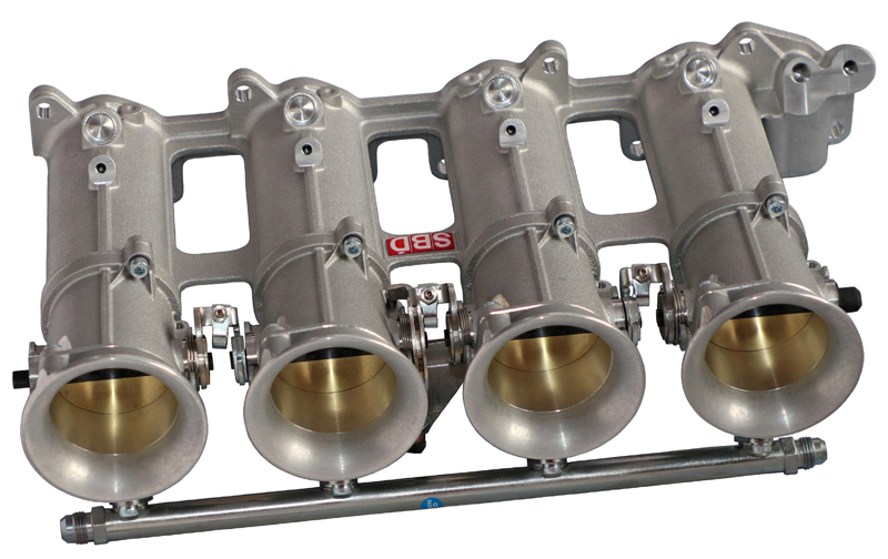
SBD taper throttle body kits are made up from 4 single bodies (on a 4 cylinder engine) which taper from the ram pipe end down to the manifold face, with a butterfly in the middle. the taper then continues on through our inlet manifolds to the cylinder head.
The main advantages of using a tapered singled body over parallel bodies & slides that we have found in tests are:
1 – Being individually adjustable they can be perfectly set-up.
2 – We have found that the use of a taper that continues the shape of the ram pipe right through the throttle & manifold up to the valve, has improved torque through almost the entire power band.
3 – Also we have found that the use of a butterfly in junction with a taper has improved throttle response. With our latest development of careful injector positioning and angles we have managed to improve response and peak performance even more.
4 – The peak BHP that we have seen from the tapers with butterflies is better than we have achieved in similar tests using parallel bodies, barrel throttle bodies or a slide throttle assembly.
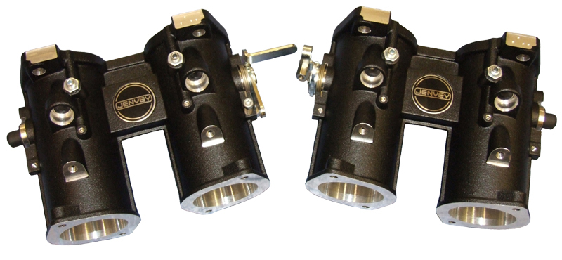
Multi-throttles are pairs of parallel throttles which look almost identical to carburettors, but without float chambers. All our multi throttle kits use throttle bodies with idle for fine adjustment of idle mixture & balance. They are available in 118mm standard Long type (the same length as a normal carburettor).
We are also asked regularly about the difference between direct to head and twin/parallel throttle bodies, they both produce about the same performance, although the direct to head has the manifold cast into the assembly which makes it neat to look at. The advantage is that the separate inlet manifold and throttle bodies is that they are more suitable to mounting throttle linkage kits, they can be fitted where the throttle bodies join the inlet manifold either above or below depending on customers preference. The direct to heads only have provision to mount the throttle linkage underneath up against the air filter backplate mounting.
These types of intake systems, although produce reasonable performance, we consider to be the basic throttle body types, where if you are looking for ultimate performance either now or in the future, you should look at SBD taper throttle body designs.
The latest development of our taper throttle body designs comes supplied with a simple cam design throttle mechanism ready to accept a throttle cable, the inlet manifolds also include the most up to date port shapes. We are always working to improve the performance of all our engine kits and the new port design matches perfectly with our latest CNC cylinder head work, however even if you aren’t using our cylinder heads you can potentially gain advantage by matching your cylinder head to our inlet manifolds. Certainly all those who have purchased our taper throttle body systems are extremely complimentary about it and the reports are continually coming in with very positive results.
Category:
Fuel Injection
Question:
I have just bought a standard XE engine and I want to tune the engine further as time & funds allow. Would you recommend for my initial spec carbs or injection?
Answer:
I would always recommend fuel injection over carbs. For example you are looking for between 180 – 200bhp, whereas a standard XE engine on carbs would produce in the region of 180bhp. A standard engine on tapered throttle bodies would produce 200 – 210bhp. With the advantage of improved response and driveability, not to mention very good fuel economy.
In theory, you should be able to get the same amount of air through a carburettor and you could do through a throttle body of a similar size. There are many reasons why in reality it does not work quite as you would expect. One of the simplest being, that if you fitted a choke size to your carburettor the same as a throttle body you may well be able to get fairly close, but when you are not trying to achieve peak bhp the gas speed is slower. A fuel injection system is programmed to supply the fuel as the engine requires, whereas a carburettor can only supply the fuel that the vacuum of the engine can draw through it. This is why carburettors have different choke sizes fitted. You have to compromise on peak power over power through the entire rev range. There are many other reasons that come into play, I could literally spend days describing some of the tests we have carried out over many years.
One of the tests we carried out was to take a standard 2.0L XE engine, and place it on the dyno, we initially ran the engine on carburettors and optimised the settings, we gained to sets of results. An engine that was drivable throughout the entire rev range obtained approx. 180bhp. We experimented with much larger choke sizes to see what could be achieved, we managed to push the horsepower up to 190bhp but the engine was completely undriveable on anything other than peak rpm. We then took off the carburettors and fitted multi-throttles, the engine instantly produced 195bhp and was even more drivable than the carburettor engine using the smaller chokes. After carrying out all the tests on multi-throttles, we then changed to taper throttles, we managed to produce 208bhp, the engine had slightly more bottom end torque than the multi-throttles, a small increase in the mid-range torque and the torque hung on much longer up the rev range, which was why it produced 208bhp.
On each of the systems we tested, we found it necessary to optimize the exhaust manifolds as well, as each system had a slight variation in its requirements to produce it’s best.
Over the years we have experimented with various engine specifications and have never found that even if an engine does produce, let’s say 20 horsepower more than another but over a very small power band, that the engine with the wide power band makes the car quicker round the track.
If you wish to progress slowly, which is what many of our customers do, we use the same throttle bodies on most of our fuel injection kits and as I am sure you can appreciate, as you try to obtain more bhp, you get smaller returns for ever increasing cost. As a rule of thumb, if you convert from carbs to fuel injection, we would normally expect to see between 10 & 20 bhp gains (this depends on carburettor and choke sizes) with a huge improvement in driveability. You could then improve your engine in stages as your budget allows. The system could then be programmed on the road, rolling road or dyno to achieve the optimum from your current engine.
2021 Update
This FAQ was quite written quite a few years ago and effectively nothing has changed, the only thing that has made it more likely that you would go for throttle bodies is that carburettors are now considerably more expensive than throttle bodies because they are manufactured in small quantities since they are not used as often. Also when you get them to a rolling road, they take a lot longer to set up than fuel injection and it is extremely likely that you will need to change jets, chokes and possibly other parts within the carburettor to optimise your settings, these are not cheap and since most rolling roads do not deal with carburettors any longer, the parts may not be available.
Category:
Fuel Injection
Gearbox & Clutch (9)
Question:
Can gearchanges be controlled by the gear position sensor only attached to their gearbox?
Answer:
The 9A range of ECUs have a wide range of powershift options that can be configured from a Single Cut to a Full Closed Loop Control set up and in the most advanced options can rev match.
The problem with trying to do a gearchange with a gear position sensor only is that the threshold required to trigger a gearshift is very small and any noise that manages to enter into the signal either from an external device such as a coil or alternator or even slack in the transmission can make the ECU believe that a gearshift is being requested and because this is its only means of input, it has to believe it. Therefore the problem is that the ECU has to cut engine power even if the driver is not touching the gearstick or paddles, and the driver then thinks they have misfire. So we do not use or recommend this strategy.
We recommend the following; use either a switch in the Gear knob or in the gearbox or a strain gauge, then when the switch sends a ground signal to the ECU Powershift pin (stain gauge changes voltage), the ECU knows it is ready to do a gearchange. If it is a Single Cut only, this is sufficient. On more advanced set ups such as Fully Closed Loop, the gear position sensor then gives information to the ECU as to how far the gear drum has moved and it can make decisions based on this information. For more advance options such as Closed Loop, we suggest that you contact one of our agents who can either set it up for you or provide remote technical support to set it up on your car. We can carry out this kind of work for you, but you would need to have had your car wired first.
Category:
Gearbox & Clutch
Question:
What are the Neutral Button functions on Gearchange system?
Answer:
You must fit a Neutral Button, otherwise the ECU will not know when you want Neutral. The Neutral Button does two basic jobs :-
1 – Select Neutral.
2 – Selecting a gear if no ‘Clutch Switch’ is fitted. If a clutch switch is not fitted, then the driver would need to press the neutral button to tell the ECU that he is ready to select a gear, he then pulls an up or down paddle whilst holding the neutral button. The ECU will then select a gear. This stops the driver or anyone else accidently pulling a paddle and selecting a gear if the engine is running.
Fitting a ‘Clutch Switch’ means the ECU knows when the clutch is down (I use a brake light pressure switch Banjo Bolt quick and easy to fit). You will then be able do the following.
1 – Select a Gear without pressing the Neutral button first.
2 – Start the Engine when in Gear.
Category:
Gearbox & Clutch
Question:
What are the reasons for Clutch & Launch switches?
Answer:
Clutch Switch is for sensing pressure on the Clutch pedal. This effectively allows the ECU to sense that the driver has rested his foot on the clutch and potentially disengaging the clutch mechanism. This allows the ECU to do two things, prevents the gearbox doing down shifts and damaging the engine, e.g. if the car was in top gear the driver rests his foot on the clutch, the engine is disengaged from the clutch and the rpm drops. The driver could effectively then downshift from top to 1st gear, let the clutch up and obviously destroy the engine.
The second use for this switch is that when the driver is in the car, the system senses that the clutch is being pressed and therefore allows the paddles to select a gear safely.
If at least one wheel speed sensor is fitted, a minimum speed can be programmed into the ECU so that the engine can go down the gearbox. This is normally programmed to the maximum rpm below the rev limiter in first gear e.g. if 1st gear was 60mph at 10,000rpm*, then unless the wheel speeds were below 60mph when the clutch was pressed, then no gear changes will happen until below that speed.
*Please note that this is designed to help save damage to your engine, but it cannot protect against rate of change damage e.g. if your engine is at tickover for example and the wheel speeds are at 60mph, when the clutch is released at tickover, the engine acceleration is likely to be too great and the valve train will lose control, this can cause valve to piston contact and damage.
If a clutch switch is not fitted, then the driver would need to press the neutral button to tell the ECU that he is ready to select a gear, he then pulls an up or down paddle whilst holding the neutral button. The ECU will then select a gear.
The Launch switch is used to control Launch and provided the Launch circuit is fitted and set up, this can be used in a similar way, but you must remember that Launch is designed to operate when the clutch is on the floor and therefore if the driver simply rests his foot on the clutch pedal then he can actually have the clutch disengaged but not have triggered the switch and therefore downshifts could still occur and damage the engine.
So my suggestion is normally Clutch switch is most important for safety and should always be considered the first option and the Launch switch is for Launch and only used as a back up.
Categories:
Gearbox & Clutch,
Launch & Traction Control
Question:
What can I do for gearbox control, there are a lot of products on the market and it is very confusing?
I will give you a little bit more information on the gear change systems and how they work, then hopefully this will give you an idea of what can be done and what the pitfalls are if your system is too simple.
Answer:
I decided to design a gearbox control system in 2003 and it was ready to run for the beginning of the 2004 season. When we initially tested the car, all seemed fine. But as we got to the first event and subsequent events we discovered the gear changes were becoming erratic and as the season progressed, the changes got worse and worse. I looked at the systems before designing ours to see what everybody was doing and assumed that a Gearchange was simply a question of cutting the spark and then pushing it from one gear to the other. At the end of the 2004 season I removed the electronic system and put a manual system onto the car, similar to that you have seen on our web site using a cable or rod operated system which was connected directly to the gearbox. I logged all the information over the season to discover what was going on. We found out that no two gear changes ever take the same amount of time, no matter what the conditions and if the vehicle happens to be wheel spinning, gear changes take even longer.
When you are driving with a gear stick or gear lever or anything where the driver or rider is connected directly to the gearbox, without realising every time you carry out a gear change you actually subconsciously adjust the way you change gear, whether it be foot or hand operated clutch. So when you produce an electronic system to reproduce this, a simple system which we had originally come up with is not capable of doing this. If you simply put a long time for the spark to be cut and the gear changes faster, the gear changes feel as if they take forever and if you put a short time in there, quite often a gear can be missed and the gearbox will become damaged if not straight away over time. So we very quickly learnt that you need to produce full closed loop system which works out drum rotation of the gearbox and therefore the time for the power reduction of the engine can be varied according to how fast the gear change occurs, therefore making a self-adjusting system.
This is just a basic explanation of how it works. Our system is actually considerably more complex than that, so it can actually work out if the gearbox is actually going to change gear, what to do if it doesn’t want to change gear and so on. Next comes the mechanism that you are using to change gear. When you change gear with a bike or car gearbox, you never actually kick it into gear, or smash the gear stick into gear, you actually feel it going into gear smoothly. So the system you use to carry out the gear change needs to be able to give a gentle, yet precise and smooth operation without damaging the gearbox itself. It is not a question of how much power or how fast you can move the stick, as you would simply damage the transmission.
I spent a further 5 years designing and testing our system, so that now that once it is set up it can self-adjust to suit most gearboxes. But this involves quite a few complex components and a powerful ECU that controls not only the engine but the gearbox itself. In fact to give you an idea of how complex it is, if the system senses that the gearbox does not want to change gear, due to the fact that the dogs are jammed or locked for any reason, because the ECU that controls the engine also controls the gearbox, it can do very precise control. So sometimes it fires one spark or removes 1 spark in order to unlock the dogs. This would be impossible for a piggy back system or standard ECU as it cannot know when each spark is going to be delivered.
There are a few high quality systems available on the market which are extremely good, but they are not cheap. The simple system that is listed on our web site which uses the original gear stick or cable is a fairly basic design and allows you to go for faster gear changes, but because of the driver actually being able to feel the gear changing through the lever or paddle, this adjust how the gear change occurs. Any system that is fully electronic e.g. where the driver is not directly connected to the gearbox, would need to be a closed loop design to function correctly in all conditions. With a simple system that simplifies a solenoid or actuator has its limitations and maybe ideal for use with a driver who is disabled or for casual driving where the user understands its short comings.
This is why we only produce the two types of system. Either one where the driver is still directly connected to the gearbox by a mechanical mechanism or a full gearbox control system.
2021 Update: The gearbox control strategy has been completely rebuilt and redesigned from top to bottom using everything that has been learnt in the past to produce a more advanced system to further improve gearbox control. The biggest change is that we now use rev matching, this means that the ECU looks at its next target gear and calculates from gear ratios as to what the rpm needs to be for the next gear and then once the gearchange begins, the rpm is then matched to its target gear, but obviously once the gear change has started effectively the two halves of the gearbox become detached from one another and on the more advanced set ups, which we recommend with 4 wheel speeds, the ECU is then able to work out from the driven wheel speed information the exact rpm required, even if the wheel speeds change during the shift e.g. if you are wheel spinning during the change, the driven wheels would then slow down and the ECU would adjust the rpm to ensure the revs are correct to go into the gear. The same would apply if you lock momentarily the driven wheels whilst downshifting, so the ECU is always accounting for the actual speed that the target gear that is asked for.
Category:
Gearbox & Clutch
Powershift set-up issues
Question:
One of our trade customers was having problems with a powershift set-up on one of their customers cars and asked for some help, he had set up the map using the settings from another car which has worked well.
The car was an Escort with a VX and Elite IL300 box and the description of the symptoms was; “Just been out in the car and it still isn’t working correctly, it’s very harsh when it comes back on power, not a nice smooth cut at all. It all seems too harsh and needs smoothing out. The setup is just using an ignition cut, cutting the spark, so it’s very on and off. The setup allows for torque reduction + recovery, can you tell me a bit more about these settings and also why these aren’t been used? There isn’t any information available about the MBE settings and if I fiddle with them without knowing their functions, it will end up causing issues.”
He also asked: When we have spoken in the past you said you had not found the need to use the torque recovery and that ignition only worked very well. Hence my using the same options. Could you provide any advice as to possible solutions. I notice on the paddle shift set ups I have looked at the “Finish Upshift Drum Rotation Threshold” is at 70% but on the flatshifts its 100% – could this be the issue?
Answer:
Always make sure you are using the latest software, please check our website.
I suspect you have 2 potential issues; the first problem will be how the power shift is triggered. Quite often some of the gearboxes have an adjustable switch or sensor and what the manufacturer quite often does to ensure the powershift works is to make the switch trigger too early. This means that when the gearstick is pulled that instead of triggering just at the point of disengagement, it is triggered much earlier, this effects both single cut time set ups and full closed loop set ups. When used in the single cut time, it means that the time has to be extended to cover the fact that when the driver pulls the gearstick, there can be quite a length of time from the spark being cut before the dogs of the gearbox are actually disengaging and by the time the gearbox has completed its change, the driver will be able to feel this huge delay making for quite often and uncomfortable gear change. When using the closed loop version the same issue applies, the trigger again will be too early and although the gear change time is able to vary due to the ECU knowing the drum position and able to complete the gear change when it reaches a pre-programmed position, it is extended due to the early trigger.
In order to alter the trigger point, you will need to discuss with the manufacturer of the gearbox how this is done and experiment with the trigger point according to the manufacturer’s instructions. This could be done by shims or adjustable screw to move the switch.
Once you have sorted the start point, then you will be able to adjust the cut time if using a single cut set up but because no gear changes are ever the same, care must be taken not to shorten the cut time too much. A single cut is also not suitable for cars that could potentially be wheel spinning during gear change. It is always best to use closed loop set up using the trigger to initiate the gear change and drum rotation to complete the gear change. This way the MBE system self-adjusts to the variation in time taken for each gear change.
Due to the fact that every manufacturer of gearbox works slightly differently, therefore the gears drum rotation will also vary. You should experiment with the percentage of drum rotation for completing the gear change. When set to 100%, the power will only re-instated once the gearbox drum has completed its rotation. You can experiment with shortening this value and it will speed up the gear change. Again great care must be taken if the value is set too low, although the gear change would become very fast, if the dogs have only just engaged there is a possibility that damage will occur due to the fact that the power is being re-instated too early. We find that most car gearboxes can go down to 70% of drum rotation and bike gearboxes down to 79%, but it is suggested that you start at 100% and slowly reduce this value due testing. The difference between cut and retard; cut simply removes all the sparks and retard will retard the ignition so the engine produces no power. Cut is simpler and if all the above are set up correctly, the gear changes should be very nice. If you use retard, it can be smoother but produces other issues; whilst retarded the engine will be producing more heat and if the engine itself is prone to any issues, it could amplify an inherent problem with the engine. Also when the ignition is in a retarded state, the fuel is no longer ignited in the combustion chamber, it will be ignited in the exhaust producing additional noise because of this. A combination of cut and retard can be used but more information, as far as suggested settings are concerning, are within Easimap 6.
Categories:
Gearbox & Clutch,
MBE Management Systems
Question:
How long does the air last in the pneumatic gearchange system?
Answer:
The valves used are an industrial design and will slowly leak air over time (as used by everybody). Air loss varies depending on many variables, but I would normally suggest a minimum would be about 2 hours from fully charged and normally fully discharged by the next day, although I have seen cars hold air for over a week. There is no fixed time. I am always paranoid that the air will run out on a run and because of the noise in the paddock you cannot hear air leaks at the event, so I charge the air on my car after every 1 or 2 runs to ensure it never runs out.
Category:
Gearbox & Clutch
Question:
Does the MBE have an option for queued gearshifts?
Answer:
We did consider adding an option for queued gearshifts but have not found it necessary, most drivers who have used our system including those converting from other makes of gearshift systems find ours usually faster on the shifts (mostly due to the integration of engine and gearbox software) and not thought it necessary once tested. My own personal thoughts on queued downshifts is that when you approach a corner, if you don’t know what gear you want you would just keep tapping the paddle hoping you would get enough downshift. If you do know which gear you want, you again have to think how many times you have to hit the paddle, if you then approach the corner and something has changed you may have to hit the paddle for more gear changes. All of the these options require additional thought by the driver and these thought trains will be different based on the discipline you are competing in, simple pull and hold means it will only change down safely and if you let go of the paddle, it will stop changing down. If you simply want one gear change, you tap and release the paddle. I have found that if we attempted to queue the gears, if it wasn’t safe to downshift when the paddle was hit and a change occurred later, this was very distracting for the driver and he didn’t know what point the change would occur. This was particularly uncomfortable if an unexpected gear change happened when the driver was making an unexpected change in direction avoiding another car or obstacle.
Category:
Gearbox & Clutch
Question:
I purchased one of these a while back. Works great however I’m not sure I got the spacing right. I noticed some slight scuffing inside the cylinder when I changed the seal. What is the correct length of the spacers – or at least the difference in length of the 3 spacers?
Answer:
There is no correct length a such for a spacer. The hydraulic slave cylinder set up is dependant on each installation. The way we normally set up our hydraulic clutch mechanisms is to assemble the clutch with no drive plate in, so in theory the fingers are as far back as they will go towards the gearbox as in a fully worn out state. We then fit a long spacer onto the hydraulic clutch mechanism, ensure that the release bearing is pushed back on the slave cylinder as far as it can go and then press the gearbox and bell housing against the back of the engine and measure the gap between the bell housing and the block. For example, if you had a 10mm gap, the spacer needs to be shortened by 10mm.
If the bell housing goes all the way against the engine, then you need to look through the release mechanism hole or inspection access of some kind and check the distance between the release bearing and the clutch fingers. If there is a gap when the release bearing is fully pressed as far back as it will go, remove the bell housing, pull the bearing and the slave cylinder forwards by slightly more than the gap you would appear to see through the inspection hole. Then reassemble again, this time the release bearing will be pushed back by the fingers as you assemble the gearbox onto the back of the engine until it stops. You can then remove the gearbox again and check the amount that the release bearing is proud of its stop. Then you will need to add this distance to the length of your existing spacer. This is not the overall length you need for your spacer.
Category:
Gearbox & Clutch
Question:
I have a problem with my Westfield. It seems like the car is riding the clutch when you put your foot down. It drives fine at normal speed, but when you floor it you just get engine revs. I have a SBD Standard size lighten flywheel, (the one with posts, a SBD Organic clutch and a SBD hydraulic clutch kit. Some one suggested that as I have been using the car the clutch has worn down so now the spacer in the hydraulic clutch is no longer the right size. So the fingers of the clutch cover do not have the space to come away fully. So do I need to remove the engine and get the spacer removed? Can you offer any advice to me? I have tried bleeding the clutch and it did not help.
Answer:
It sounds as if you are half right. When the assembly was fitted, no account was taken to allow for clutch wear. You must dry fit the clutch cover with no clutch plate fitted, then slide the gearbox with the complete slave assembly and spacer fitted to the gearbox. You should then slide the gearbox onto the back of the engine. Now because the spacer is likely to be too long, you should be able to measure a gap between the block and bellhousing face. Say for example, it was 10mm, the spacer should be shortened by 11mm. This means that when the clutch is fully worn the slave cylinder/release bearing can never apply pressure to the clutch fingers. The extra mm is just a safety margin I always use.
Never leave the spacer out altogether, because the clutch slave only has a certain amount of travel. If you were to leave the spacer out completely, the chances are you could fire the hydraulic slave so far out that all the fluid could leak away.
Category:
Gearbox & Clutch
Hayabusa Specific (8)
Question:
What are my options for new camshaft profiles?
Answer:
There are effectively 3 options when it comes to Hayabusa cams:
1. Regrind a standard cam profile, this reduces the size of the cam in order to increase the lift and duration. You would then have to run a thicker shim to take up this difference. You are also limited by how much material that it is possible to remove from the original cam in order to produce a larger profile. We produce 2 profile designs; the first only require a pair of standard Gen1 camshafts. The second larger profiles require either a pair of standard Gen1 inlet cams or a pair of standard Gen2 cams because these cams have more material.
2. Hard weld on to standard cams, this is not something that we do. The problem with this process is that the material can sometimes then come off the cam profile causing damage to the cam and valve train.
3. Use steel billets to grind fresh profiles, which allow within reason any profile to be ground. The limiting factors are as follows, the steel billets are of a similar hardness to the follower so to prevent the 2 components wearing each other away, we would use either a DLC coating on the cam profiles or the followers to prevent any chance of this happening, but this is extremely expensive. The next factor is that as you increase the lift of the cams, the springs need to be significantly increased in strength. This creates extra load on the valve train, chain, guides, etc and also reduces their life.
The choice is dictated by your budget and the life expectancy that you hope to achieve, so if you want to do a drag run and have to rebuilt it every few runs, then you got for the biggest cam. If you wish to do a hillclimb, you go for something milder and if you wish to do sprints or racing, you look at something milder again.
Category:
Hayabusa Specific
Question:
I’m looking for a 100mm diameter dry sump oil tank because of installation issues. I noticed that the one on your site, but it says it can’t be used with a Hayabusa, why?
Answer:
The biggest problem with Hayabusa engines, in all bike engines, is the gearbox, clutch and generator areas in the engine. These can fill up with oil under different conditions e.g. cornering, accelerating, braking, etc which means that they can retain a lot of oil under these conditions and only when the area is full of oil and no longer any space, can it reach the bottom of the engine so be evacuated by the scavenge pumps. These creates 2 problems, most important of which is that you can end up with an excess of 3 litres of oil within the engine. The engine also normally retains between ½ to 1 litre when running. This means that you can end up with in the region of 4 litres of oil within the engine, so we have found the minimum capacity for oil within the dry sump tank needs to be 5 litres of oil (this excludes what is in the pipes, oil cooler and actually within the engine when running. Anything less than that will cause a problem, not just due to the lack of oil in the tank but the secondary problem which I will describe now.
The top of the dry sump tank is used to separate air from the oil, there will always be air extracted by the scavenge pumps and this can be up to 90% more air than oil. The oil is sprayed around the top of the tank and jetted as a film of oil around the wall of the tank. This helps the air to separate and by the time it is spun round the tank, the majority of the air is separated out. The taller the tank, the better this functions and the less complex the tank needs to be, the shorter the tank the less time available for separation to take place. Ideally you need a minimum of a 1½ litres of air space before the oil level is reached.
The tank we recommend for the Hayabusa engine is made taller than the original design, its first baffle has about 1.5 litres of air space, you can see the detail of the construction on the website. This tank is designed to separate air further as it passed through each level and the lowest level in the tank, in theory, does not allow for oil movement, but must be completely filled with oil only as any air left at this point would be compressed by the oil system and create catastrophic failure of the engine. This tank has an oil capacity of 5 litres, the smaller tank that you are looking at was originally designed for the Vauxhall engine in sportscars, the Vauxhall engine can run on 3 litres of oil in a tank, this meant that the tank itself has a large area for the air, it has no baffling due to its small diameter and its height. The Vauxhall engine only has small areas that the oil could congregate, so therefore would not retain as much oil as the Hayabusa.
If you do the calculations on a 100mm diameter tank, you require a tank in excess of 600mm tall and this is probably still not sufficient because you are more likely to require over 2 litres of air capacity due to the lack of baffling to allow the air to separate. Also due to its smaller diameter, you wouldn’t be able to incorporate the small internal design of the larger tank and without extensive testing could prove disastrous.
Category:
Hayabusa Specific
Question:
I have a 1999 std Busa engine that I’ve mounted in a custom made chassis. I plan to keep the motor stock as its fast enough for what I want. I’ve looked at your web site and think you have what I need to get it running?
I have all the original loom and ancillaries but it looks way too complicated and over the top. I would like a simple loom and I assume a new ECU. In time I want to have a power shift on it but that’s another budget. My idea is to have a paddle shift off the steering wheel.
Do your looms just plug in? What electrics do I need to save from the old loom? I assume I need a charging circuit and a ignition circuit? I’m not too worried about lights etc as these can easily be done on a separate switched circuit.
Also do I need to alter the charging rotor thing? If so is there an exchange option for this part? How does the old one come off?
Have you a full typical circuit diagram showing what parts of the existing loom/wiring I need to save? The engine does run, but I know it can be much simpler. In your loom do you cut out most of the silly sensors? Does the standard fuel pump (mine is on the back of the engine) plug straight in? Is it a simple plug in start up and go system?
Please can I have some advice, I don’t want to make an expensive mistake here.
Answer:
The installation of our system will be extremely simple by comparison with what you have there. Most of our harness will simply plug in to the original coils and sensors and what sensor you don’t require will simply be eliminated. The only update we have carried out recently to our wiring harness is to change the injector connectors to make them more user friendly for future engine updates, but it is a fairly simple process to either add or make simple adaptors to convert from the standard Suzuki injectors to our wiring harness (there is no cutting of our wiring harness). If you are OK with a heat gun and a crimp tool, it is no more than 1/2 hours work. There are instructions within the installation instructions of the kit that show you in pictures how to modify the connectors, which you would remove your existing harness or there is an option to buy ready finished adaptors.
The charging circuit is relatively easy to modify but we do make a simple charging harness, which simply plugs into the generator and the regulator pack and then gives you 2 wires for positive and negative.
Your original fuel pump can be used, the only issue you could potentially have is that on the motorbike the petrol tank is mounted above the engine and therefore the fuel is gravity fed to it. When fitting it to a car you would need to ensure that the pump is mounted lower or at least at the same level as the bottom of the fuel tank, so you may need to reposition it. Alternatively, if your budget allows, you could a more traditional supply and return system and replace the fuel pump, fuel rail and fuel regulator to suit.
The generator trigger wheel is easily changed with the correct Suzuki tool or if you are suitable mechanically minded, it wouldn’t be too difficult to produce something for yourself. Effectively you need to remove the generator cover, then there is a bolt retaining the generator rotor which locks it on to a taper and key. You simply undo the bolt, which exposes an external thread, the Suzuki tool is then tightened into this thread, there is then 2 flats on either side of the generator, which can be held with a spanner. This then pulls the generator off the crank, the generator itself on the early engines such as you have, has 8 teeth and you require a 24-1 which is fitted to the 2003 – 2007 engines and will fit directly with the Gen 1 generator. Alternatively you can fit the 24-2 trigger wheel from the Gen 2 engine, but you will also need the generator windings as well as the rotor because they are a slightly different size. We will need to know before programming your ECU. It is best to hunt through eBay or similar to look for a second hand unit, new units are available but are very expensive.
Once the system is fitted and the throttle position sensor is adjusted, which can be done with a volt meter, with the standard map loaded which we would supply in the kit, your engine will be ready to run and use. Please refer to our Instruction Sheets for the wiring harness fitting instructions.
It may be worth a phone call to speak to me directly as quite often questions you may feel are complicated can be simply answered on the phone. The system you are looking at is, we believe, the simplest on the market and we supply this kit worldwide to trade and retail alike. If you wish to upgrade your engine and other components associated with it, it can be easily done. You mentioned about Powershift, the standard wiring harness that we supply has a Powershift connector built in and the ECU will be programmed and ready to use it as standard. You can simply then order the Powershift unit, which you fix to the lever on the gearbox and connect the other end of the cable to your steering wheel paddle or gear lever.
Category:
Hayabusa Specific
Question:
I have a 2003 Westfield Megabusa with a 99 Hayabusa and it has your SBD dry sump pack. The oil temperature gauge never seems to get much above 65-70C on a trackday after circulating for 15-20 minutes. I suspected that the gauge wasn’t reading correctly, but I’ve tested it static and the reading on the pipe at the oil cooler is the same as on the VDO gauge, around 65C according to the temp sensor for my multimeter.
The oil system takes just over 6 litres and there isn’t a thermostat. I have an oil cooler with core dimensions of 360W x 193H x 50D, which to me looks very large for a 1300cc bike engine. The previous owner replaced the oil cooler, and decided to fit a bigger one on the “bigger must be better” principle!
I’m under the impression that the oil temperature should be around 100-110C when working hard. If so, what setup would you recommend in conjunction with the dry sump kit?
Answer:
If your engine is running the oil temperature you are seeing, this will be a first. Suzuki bike engines were originally air cooled, then oil cooled and then finally water cooled, but when they produced the water cooled version, it was effectively only added on top of the oil cooling design, which instead of virtually same amount of heat transferred into the oil system as in to the water system, hence the reason for running a very large oil cooler. Keeping the oil temperature under control helps to keeps the water temperature under control as well, due to heat transfer within the engine.
You have to remember that the oil temperature you are seeing is after it has been cooled, before it re-enters the engine and therefore it would be lower than if you measured the oil temperature within a wet sump for example. Normally cars such as sportscar and single seaters have space to mount the radiators and oil coolers on separate sides so they both get clean air flow and would be able to achieve efficient cooling. Normally on cars such as the Westfield, this is very difficult to achieve because all the air flow has to go through the nose cone and therefore either the oil system or water system will have an advantage. Obviously we don’t know your installation and how you have fitted the radiator and oil cooler, but if they are both achieving good efficiency, it is some that I am sure others including us would like to know how you have done it.
Since we don’t know how your installation is done, we can only give some basic advice. The Hayabusa itself is effectively a road bike engine, which has reasonably large clearances so it can be driven quite hard when not up to optimum temperature, otherwise they would be engine failures on the road bikes. As the temperatures rise the engine case expands, the clearances increase and the oil pressure will drop. When you get up to what would be called optimum oil temperature, when the oil is at its most efficient, the crank cases are potentially larger than would be optimal so we quite often like to see the engines running at a minimum of 60-degC and 80-100-degC, even though the oils can work at 120-degC the slightly lower temperature help to keep the bearing clearances tighter. Remember that the oil temperatures you are seeing, if correct, are after cooling.
Fitting thermostatic controls adds weight and complexity and not something that we try to do. Fitting a smaller oil cooler means you limit your cooling capacity and if you want to slightly increase the oil temperature, the common practice in all motorsport is to blank off parts of the oil cooler effectively reducing its size, you then have the ability to increase or decrease its efficiency very quickly. I would also check the oil temperature with a laser temperature gun directed at the oil in the tank from the filler cap just for piece of mind.
Category:
Hayabusa Specific
Question:
Hello, I’m looking for a for a bit of information. I’m running a Suzuki Hayabusa in stock condition. I’ve purchased your dry sump and tank which is working quite well. We set the engine up with dual radiators, and one single oil cooler. Water temps have been 170-180°F, oil temps have been 240°F and climbing. We have not allowed temps over 240°F. We’re not really sure what is normal oil temps for this engine, but were concerned were on the edge. Can you offer some info on this and some possible solutions?
Answer:
The Suzuki Hayabusa engine, as with many Suzuki engines, has evolved from the oil cooled engines and almost as much heat is transmitted into the oil system as the water system. The temperature of your oil at 240°F (116°C) is ok, but because the engine expands the bearing gaps increase dropping oil pressure. If the temperature could be kept closer to 230°F (100°C), this would help oil pressure as well. My suggestion would be to increase your oil cooler size significantly. You may also find that once you have managed to reduce the oil temperature, that this will also help to control your water temperature better as well.
When your engine is cold (oil temperature of 0 – 20°C) at tickover, I would expect to see between 50 – 60psi approximately and if revved over 100psi. Obviously this is not recommended until the engine is hot.
As the oil temperature rises, the tickover oil pressure will drop quite quickly and I would expect to see approximately 20psi when oil temperature is 60°C. As the engine is revved, peak oil pressure will probably be just under 100psi. I would recommend that you try and maintain between 80 – 100°C, this way your oil pressure at tickover will be in the region of 7psi and peak oil pressure 60 – 70psi.
The further the temperature rises, the lower the pressure will get, this drop in oil pressure is caused by 2 main factors; first of all the engine block grows dramatically with heat causing increased clearance between the bearings and the crank and secondly the oil itself gets thinner with heat, this is quite normal. If your engine was running a standard oil pump gear as opposed to our uprated gear, I would expect to see a 10% reduction in oil pressure throughout the range. It is not uncommon with oil temperatures in excess of 120°C being tickover oil pressure as low as 2psi and peak oil pressure down to 35psi. The most important thing to look out for is that the oil pressure follows the rpm, if you see any drops in oil pressure at higher rpm it is likely that your oil tank is carrying insufficient oil and therefore oil surge is occurring, which will cause engine damage.
Category:
Hayabusa Specific
Question:
What are the differences between the Hayabusa Gen1 engine and Gen 2 engine?
Answer:
The Hayabusa Gen 2 engine 1340cc has been around now since 2008 and therefore more readily available. The earlier Gen 1 engines were discontinued at the end of 2007, this means that the engines are now getting quite old and in shorter supply because of its popularity.
The Gen 2 has quite a few advantages over the earlier engine; the gearbox was dramatically improved and some of the shortcomings in the original design and the weak output shaft were overcome. The slight increase in engine stroke gives a nice improvement in torque and the engine having a better design of piston and higher compression has allowed the engine to produce the performance in standard form of a reasonably tuned Gen 1 engine and with the added advantage of the increased torque, a nicer all round package. The cam profile are also slightly larger, which helps add to this.
The downsides to the Gen 2 engine is that the valves are now titanium and they have seen failures in motorsport applications. Also the valve springs are now a single valve spring where the Gen 1 has a double valve spring, so a common modification is to replace the valves with either the Gen 1 valve or a stainless steel high quality replacement and fit the Gen 1 valve springs.
The barrels on the Gen 2 engine are windowed, which is fine if the bore size remains standard but if the bore size is increased, they will quite often fracture, so it is recommended for big bore versions that the Gen 1 barrels are sourced because they are much stronger but they are becoming harder to find due to their age.
The crankcase of the Gen 2 has been thinned around the area where the head studs or bolts fit into, this is normally not an issue unless you are using a turbo application.
Category:
Hayabusa Specific
Question:
I have got a Hayabusa 2004 Gen 1 engine with nothing special on it at the moment. Is running the 4 short airhorns is a better option?
Answer:
The use of a combination of air horn lengths has a tendency to smooth the torque curve, the longer air horns promote lower to mid-range torque and the shorter air horns improve the upper mid-range torque to peak bhp. If your engine is solely being used at higher rpm on the standard 1299cc engine, then potentially 4 short air horns will be the preferred option.
If you are using a long stroke engine in the future, then 4 longer air horns would be the best option for that engine because the engine does not rev as high.
Category:
Hayabusa Specific
Question:
I am currently working on a 1.6L Hayabusa and would value your opinion whether to use 4 or 8 injectors?
Answer:
The throttle body we designed for the Gen1 engine produced superior torque and power over the standard throttle bodies and during its design, we specifically worked on testing it against 8 injectors on the dyno. The end result meant that there was no advantage in running 8 injectors.
The Gen2 engine is produced with 8 injector set up as standard. We have tested the design on both 1000cc engines and the larger capacity Hayabusa versions. The standard throttle body set up with 8 injectors only increases performance when the upper injectors are used above 7000rpm and gives an increase of approximately 5bhp. The reason I believe the manufacturers have gone for 8 injectors is to allow them to move the lower set closer to the engine for emissions and then the upper set in an attempt to regain the performance that would be lost in doing so. When tested against the twin throttle body set up we have designed to fit the later spacing of the inlet ports of the Gen2 engine, we found we had a gain in performance everywhere over the standard Hayabusa throttle bodies.
So provided you are able to replace the standard throttle bodies with our throttle bodies, they will always give an improvement.
Category:
Hayabusa Specific
Lambda (4)
There are several reasons why you may or may not want to use lambda.
1. Using a narrow band lambda sensor which is used on most early emissions cars is only suitable for fine trimming the fuel whenever everything is set up correctly. It is not a device to try and fix poor idling or poor running. It must be running correctly before lambda is used.
2. If your car does not require lambda or run tight emissions control, then don’t use the sensor it only adds to the complexity. All our systems are designed to automatically disable lambda control if the lambda sensor is not seen.
3. If you wish to use lambda as a mapping aid, then you would need to use a wide band lambda sensor and the 9A4 and 9A8 ECUs would need the use of a lambda controller. Something like an Innovate LC2 system or similar. These produce an output of 0-5v, the ECU can then be calibrated based on the Innovate information to convert this voltage into lambda. You would then use this information when mapping to ensure the fuel mixture is correct at the speed and loads. It is even possible to set up the ECU to do closed loop mapping, but this is something for the more advanced user.
If you are going to have the engine programmed professionally on the rolling road, it is always best to take advice from the expert that you are confident to deal with. Every rolling road and dyno has their own way of doing things. If we were to do any programming for you some of this can be done remotely, but we would need to be able to read lambda in the ECU. So we would suggest something such as the Innovate LC2 system should be used. We can calibrate the ECU accordingly then do Team Viewer session to set up idling and low speed running before going to a rolling road and then if you wish us to do some mapping at the rolling road, we can also arrange a time to suit.
Category:
Lambda
Question:
I have a question for you, can we buy a Lambda sensor and connect it to our MBE system. And does our system contain a auto-tune system?
Answer:
As far as lambda systems are concerned, all MBE ECUs of the current spec are able to run closed loop mapping. The MBE9A4 can either run a narrow band lambda sensor, which is only suitable for emissions (Lambda 1) or an external device such as an ETAS, Bosch (professional lambda equipment for calibration) or a system such as an Innovate, which is a club level lambda sensor and controller. Both use a wide band type lambda sensor, which will then transmit a voltage directly to the 9A4. The maps can then be calibrated in the ECU to allow the ECU to do closed loop adjustments (auto-tune).
This facility is available on the high end motorsport MBE ECUs, the MBE9A9/9A6, which you can directly connect a wide band lambda sensor to.
The only time we use closed loop fuel mapping (Auto-tune) is when we are initially mapping each car/engine. The system is normally disabled after that time and on our high spec ECUs only allow limited changes to occur. This is to prevent damage if the sensor reads incorrectly. Various things could go wrong in competition conditions and if full trust if placed in the sensor reading correctly, this could be disastrous, for example, if a fracture occurs in the exhaust system or part of the exhaust falls off, the sensor could read lean and the ECU could make adjustments based on incorrect information potentially causing engine failure. Also if the sensor reads rich due to the fact that it is beginning to fail or becomes contaminated, the mixture could be leaned off again causing engine failure. So although it is a useful tool, it is only safe when correctly controlled or under mapping conditions, not during a race.
Category:
Lambda
Question:
If I want to check the engine on the track, can I fasten my laptop in the car, then start the logging in the software and drive the car for about 15 minutes, then save the log on the computer. Is it then possible to analyse the log and then verify the mapping without a Lambda?
Answer:
Without the reference of lambda, the information you would get would not tell you whether the engine mixture is rich or lean. The kind of information you are able to log is useful for fault finding e.g. if a misfire occurs and is related to an engine sensor. If you want to be sure the mixture is correct, then potentially the cheapest option is an Innovate system as these are easily available on the internet for a cost of around £250. You could either log it as a standalone using its own analysing software (depending on level of unit you buy) or with the correct calibration in the ECU, log it within the laptop.
All this is worthwhile, but involves a lot of time and effort on your part and cost involving buying the equipment and setting the ECU up with calibrations to suit. Then either you need to analyse the data or you would need to send the data to me, which again obviously involves more cost.
Our advice would be to take your car to one of our Approved Mapping Agents to be mapped professionally, they would have all the necessary equipment.
Category:
Lambda
Question:
Can I fit a lambda sensor to my engine to enable it to pass emissions?
Answer:
Your engine will need to be mapped correctly first and your car needs to be equipped with the correct exhaust system. The engine should not be too highly tuned and capable of running Lambda 1.
Lambda control should only be used as either a tuning aid or for emissions, it cannot fix an engine that has been mapped incorrectly, it is only there to trim or monitor the engine’s emissions to ensure they remain within original programmed limits.
Categories:
Exhaust Systems,
Lambda
Launch & Traction Control (4)
Question:
Would I be correct in thinking that when traction control kicks in, I should not take my foot off the throttle at all (which is the immediate instinct) but continue to apply throttle and let the electronics do all the work?
Answer:
Everybody tries to use the traction control in a different way, some drivers assume (usually the slow drivers) that it will make them faster and instead of driving the car normally, drive the car with the pedal flat to the floor and let the traction control do all the work. The way I use the traction control and many of the quick drivers use it, is to drive the car normally but when the conditions are slightly suspect i.e. the driver is unsure of the amount of grip is available in certain areas, that the traction control will allow them to use slightly more throttle and be less cautious than they would have been. That way if a patch on the circuit is found to be less grippy than expected, the traction control will give you some extra protection.
One of the best example of this, is if you are drifting the back end of the car and suddenly hit a patch of oil, you would normally attempt to come out of the throttle to prevent the rear end of the car from producing an excess slide and putting you into a spin, because the traction control can detect this sudden change quicker than you can, it will back the power off and normally allow you to carry on at the same angle of drift without loss of control. If at the same time you back the throttle off, you will actually get slower and the angle of drift will reduce.
My suggestion is that the traction control should be used to help you to maintain grip in unforeseen circumstances rather than a crutch to rely on. Drive the car, do not change your driving style but experiment under controlled conditions so you get a feel for what the traction control can do for you. Traction control can not lose you grip, it can only help you to gain grip.
One last thing that is important with traction control, which many drivers feel including myself, is that when you have a normal start or lose grip is the sensation the driver feels of the car sliding and wheel spinning is quite intense. When the launch and traction control are working, the effect almost feels as if you are going too slowly, but the only way to tell is against the clock and in most cases the smoother feeling with the launch and traction control working, the car is faster but it just doesn’t feel like that for the driver.
Category:
Launch & Traction Control
Question:
The launch control is excellent although I have a question relating to the 7 launch sectors. I understand the sectors enable differing revs to be used for different track conditions. Should I be applying full throttle pedal prior to releasing the clutch with launch governing different revs depending on the sector selected? Until now I have only applied about 2/3 pedal prior to releasing the clutch.
Answer:
In theory you can use full throttle and the rpm during the launch phase will be taken care of by the ECU. If you use too little throttle, you stand a chance of the car bogging down and dropping below the target rpm. This is because the amount of power being produced by the engine is controlled by the amount of throttle opening, giving full throttle will give the maximum amount of power possible at the target rpm selected. This means you always get a known amount of torque at every sector you use. If you vary the amount of throttle, the torque will obviously vary and you will get inconsistent starts.
This is what Trevor Willis does and he commented that when he tries to drive the car during the launch phase modulating the throttle, that the starts are not as good. One important thing to remember is that quite often lower rpm will give a better start than higher rpm, even though from the drivers seat you may fill the start is quick, the clock is the best way to tell.
Category:
Launch & Traction Control
Question:
I have a question about the use of the launch control on dry tarmac in rally use. It feels incredibly hard on the car which, with two rear wheels each weighing about 20kg, leaves me sitting on the line just waiting for something to break. Whilst I can appreciate the time benefit on sprints & hillclimbs, I am not yet convinced of the benefit of launch control on my car on dry tarmac.
Answer:
We have customers who have very fragile transmissions. When using manual launches one particular customer was breaking CV joints, driveshafts and on a couple of occasions even split the transmission in half, once he started using launch and traction control, the transmission problems almost completely vanished. Another customer, who was breaking crown wheel and pinions also gained the same improvements in component life.
So it appears that a control launch creates less stress than a manual launch, which is controlled by the driver’s right foot and the amount of grip at each moment during the launch period, which could vary greatly. Don’t forget that on the sprint cars, the tyres are normally much wider and have far more grip, the number of starts that we have during each day easily goes into double figures, particularly when double driven and so far we have seen no increased wear.
Obviously, if your transmission is far too weak for the discipline/car/engine you are competing in or damaged already, it won’t save it!
Category:
Launch & Traction Control
Question:
What are the reasons for Clutch & Launch switches?
Answer:
Clutch Switch is for sensing pressure on the Clutch pedal. This effectively allows the ECU to sense that the driver has rested his foot on the clutch and potentially disengaging the clutch mechanism. This allows the ECU to do two things, prevents the gearbox doing down shifts and damaging the engine, e.g. if the car was in top gear the driver rests his foot on the clutch, the engine is disengaged from the clutch and the rpm drops. The driver could effectively then downshift from top to 1st gear, let the clutch up and obviously destroy the engine.
The second use for this switch is that when the driver is in the car, the system senses that the clutch is being pressed and therefore allows the paddles to select a gear safely.
If at least one wheel speed sensor is fitted, a minimum speed can be programmed into the ECU so that the engine can go down the gearbox. This is normally programmed to the maximum rpm below the rev limiter in first gear e.g. if 1st gear was 60mph at 10,000rpm*, then unless the wheel speeds were below 60mph when the clutch was pressed, then no gear changes will happen until below that speed.
*Please note that this is designed to help save damage to your engine, but it cannot protect against rate of change damage e.g. if your engine is at tickover for example and the wheel speeds are at 60mph, when the clutch is released at tickover, the engine acceleration is likely to be too great and the valve train will lose control, this can cause valve to piston contact and damage.
If a clutch switch is not fitted, then the driver would need to press the neutral button to tell the ECU that he is ready to select a gear, he then pulls an up or down paddle whilst holding the neutral button. The ECU will then select a gear.
The Launch switch is used to control Launch and provided the Launch circuit is fitted and set up, this can be used in a similar way, but you must remember that Launch is designed to operate when the clutch is on the floor and therefore if the driver simply rests his foot on the clutch pedal then he can actually have the clutch disengaged but not have triggered the switch and therefore downshifts could still occur and damage the engine.
So my suggestion is normally Clutch switch is most important for safety and should always be considered the first option and the Launch switch is for Launch and only used as a back up.
Categories:
Gearbox & Clutch,
Launch & Traction Control
MBE Management Systems (9)
Question:
From what I can tell, there is about a 10deg discrepancy in ignition timing, as in the mechanical timing is 10deg more advanced which is why we’ve had to retard the ignition timing map by 10deg. I believe it has to do with me adjusting the crank angle last night. With most engine management system software, there is a parameter to lock the timing at a user specified value so that ignition timing synch can be performed accurately without any trims affecting the specified value. Easimap doesn’t seem to offer that so we are assuming it is taking the value at ~1000rpm x Site 0. Setting that area at 10deg let us to adjust the crank angle to synch but the ignition map still looks wonky. For example at WOT the ignition map is set to 10deg but mechanically it’s operating at about 20deg. The car made 146whp my setup should be in the 200whp range
Answer:
If you are not familiar with MBE ECUs. I will try and keep it simple to explain what I believe you are seeing and why you don’t understand it.
The MBE system is designed to run on many production and pre-production vehicles and for this reason, it has many features to allow the engine to run perfectly even with a large number of sensors failed. I will explain below what I think they are seeing and not understanding.
1. The MBE ECUs do not require the cam sensor to allow them to start, this helps to prevent engines from not starting where they have to have a cam synchronisation before firing any sparks.
2. When the engine starts, it starts in wasted spark mode because it does not know which cycle it is on until synchronised from a cam signal, so during this time if you are checking the ignition with a strobe, the ignition value would appear to be double e.g. 10-degrees would appear to read as 20-degrees. It could be misunderstood to be an error of 10-degrees.
3. The software allows the user to configure when the cam signal is looked at to synchronise, this is called a ‘Cam Synch Window’ in most cases, this is set up not to happen at idle due to the fact that if there is fault with the sensor or ignition offset is 180-degrees out, if the wrong information is seen the engine could simply stop because of the synchronisation on the wrong cycle.
4. Most of the synchronisation windows are set around 2500-6000rpm at zero throttle. This means that the only way the engine will synchronise is if the engine is revved, the throttle is then closed and the engine will then synchronise at that point. This is a useful tool for fault finding with no equipment. If the owner of the vehicle calls up to say my engine starts but as soon as I rev it, it stalls then you have a pretty good idea there is a cam signal error, you would then ask them to remove the cam sensor connector and repeat the test. They can then use their engine quite safely as it cannot damage the engine, it will simply mean that the coils are in wasted spark mode and the fuel synchronisation may be synchronised to the wrong cylinder but this at worst would have a small performance loss on a port injected engine.
So the information given, it looks like the timing has been checked on start up, moved the offset thinking it is synchronised, then ended up with an error of the amount the the offset has adjusted by. Unfortunately, everything that has been done will have to be reversed and then everything re-checked, hopefully this will be where all your power is going but obviously there could be something else causing an issue, so this must be kept in mind.
Categories:
Engine Programming,
MBE Management Systems
Question:
Is it possible to change a map on a Cosworth or Caterham MBE ECU?
Answer:
All Cosworth & Caterham MBE ECUs are locked during manufacture, which means they cannot be modified in any way. You can only use our CAN mapping kit & Easimap 6 software for Real Time Viewing as an aid to diagnosing faults with sensors & replacement or setting up of throttle pots.
The easiest way to discover whether the ECU is locked or not is that when you connect to the ECU using Easimap 6 and the basic CAN mapping kit, if you look at the device information which is selected from one of the icons across the top of Easimap 6, if the box comes up blank, then the ECU is locked. The same will happen if you try to access any of the maps.
Warning under no conditions, should you attempt to download anything into locked ECUs, they are designed to permanently crash and are irrecoverable.
Category:
MBE Management Systems
Question:
Could you please confirm which input pin would be desired for a pull up or pull down 5v digital signal.
Answer:
The easiest way to confirm which pin is suitable is simply to plug into the ECU with the MBE985 USB/CAN interface (basic mapping equipment MBE-MAP-KIT-3-CAN). Easimap 6 will then automatically select the correct .ec2 file to match the software as the ECU you are proposing to set up gearbox control with. You will then be able to go to programmable pins and look at the drop down option for each of the pins and see if this option is available.
Because software is continually updated and changing, new functions and options will become available over time and there is always a possibility that the software version that your ECU has different functions available and therefore this can only be confirmed by plugging into the ECU or having a copy of the map from the ECU along with knowing the software version the ECU is currently using.
This applies to all our MBE ECUs
Categories:
Easimap Software,
MBE Management Systems
Question:
What is the relationship between Current Faults and Logged Faults in Easimap 6. Presumably a fault will disappear from Current Faults as soon as the condition is resolved, but does it then remain in Logged Faults? How long do they remain in Logged Faults for? And is there a way to clear or reset the Logged Faults?
Answer:
The 9A* range of ECUs has the option to display current faults and logged faults. The current faults will only exist while it actually has that fault and then the status will return to being ok. The logged fault will only log the fault until the ECU power has been cycled.
This way if you wish to diagnose a fault and the fault is intermittent, you may miss it in the current faults section, but it would be obvious in the logged fault provided you do not cycle the ECU power.
Categories:
Easimap Software,
MBE Management Systems
Question:
Can I put one of your ECUs on my road car?
Answer:
The standard management system on your road car not only controls the engine, but a mass of other accessories fitted to the car such as electric windows, central locking, lights, etc. The system is continually monitoring to see if the car in every aspect is performing correctly and if anything is picked up by the standard ECU that is not operating as it should, as a minimum it will turn an engine warning light on and normally put the engine into ‘limp’ mode. Finding all the information that the stock ECU requires is a massively complex job, taking many thousands of hours to decipher with possibility that the next time your car is serviced, Ford update software and maps completely changing everything you have already deciphered. Although there are companies out there that offer that option, the reason we don’t do anything like that on road based cars is that you can spend many of thousands of pounds, if not tens of thousands of pounds for something that only has a short life before the manufacturer stops producing it or change the design. This means that you have little if any chance in re-cooping your development costs, which has to be spread across the number of kits you sell.
All of our systems are now only motorsport based due to the complexity involved of interacting with the standard management systems. For motorsport we replace the standard management system completely then we can control every part of the system and not be hampered by what the evermore complex road based systems.
Category:
MBE Management Systems
Question:
I have a serial based MBE system currently on my engine, which I understand is out of date now. Which system should I use now and can the existing wiring loom be used with the new ECU?
Answer:
The current type of ECU is the CAN based MBE9A* series, if you look on the web site under Management systems, full details are shown there. Unfortunately, it is not possible to simply transfer the existing map within your serial based ECU to the new CAN based ECU. It may be possible to transfer a small amount of data e.g. ignition map, normal rev limiters and throttle index map. The structure of the software and maps are so far advanced in comparison with the older serial ECUs that it is either not possible to transfer it or the amount of work required even it is possible means it would be more cost effective to provide a good base map to allow your engine to be started and then have it professionally mapped. You will need to change the wiring harness to accommodate this new ECU.
Category:
MBE Management Systems
Question :
Is it possible to configure your own CAN bus messages to be sent out on the CAN interface on the MBE 9A9 ECU? Is it capable of receiving CAN messages and acting on them?
Answer :
The CAN Bus data stream is designed for use to transmit data to either external devices, such as data loggers or data to other MBE systems. It would be possible to control other devices that are CAN Bus controlled.
For example, if you have a gearbox that has a CAN Bus system on it, it can indeed control it. The problem you have is that the manufacturer of the gearbox is unlikely to release the protocols required to control the gearbox and the same would go for any other systems fitted to production cars. If you are able to get the protocols, the software could then be written to control them with the MBE CAN data stream and depending on how complex the system, would depend on how much time was required for the software engineer to write it. This may only be a matter of a couple of days of work, which would then need to be charged to the customer requesting it.
Unfortunately, if the data stream information is not available from the manufacturer, it would be virtually impossible to write controlling software to control the CAN Bus of each product, since you have no idea of what the information requires to control it. It is like looking for a needle in a hundred haystacks. It is potentially months of work just trying to decode what is required and the cost would be far too expensive.
Categories:
CAN Based ECUs,
MBE Management Systems
Powershift set-up issues
Question:
One of our trade customers was having problems with a powershift set-up on one of their customers cars and asked for some help, he had set up the map using the settings from another car which has worked well.
The car was an Escort with a VX and Elite IL300 box and the description of the symptoms was; “Just been out in the car and it still isn’t working correctly, it’s very harsh when it comes back on power, not a nice smooth cut at all. It all seems too harsh and needs smoothing out. The setup is just using an ignition cut, cutting the spark, so it’s very on and off. The setup allows for torque reduction + recovery, can you tell me a bit more about these settings and also why these aren’t been used? There isn’t any information available about the MBE settings and if I fiddle with them without knowing their functions, it will end up causing issues.”
He also asked: When we have spoken in the past you said you had not found the need to use the torque recovery and that ignition only worked very well. Hence my using the same options. Could you provide any advice as to possible solutions. I notice on the paddle shift set ups I have looked at the “Finish Upshift Drum Rotation Threshold” is at 70% but on the flatshifts its 100% – could this be the issue?
Answer:
Always make sure you are using the latest software, please check our website.
I suspect you have 2 potential issues; the first problem will be how the power shift is triggered. Quite often some of the gearboxes have an adjustable switch or sensor and what the manufacturer quite often does to ensure the powershift works is to make the switch trigger too early. This means that when the gearstick is pulled that instead of triggering just at the point of disengagement, it is triggered much earlier, this effects both single cut time set ups and full closed loop set ups. When used in the single cut time, it means that the time has to be extended to cover the fact that when the driver pulls the gearstick, there can be quite a length of time from the spark being cut before the dogs of the gearbox are actually disengaging and by the time the gearbox has completed its change, the driver will be able to feel this huge delay making for quite often and uncomfortable gear change. When using the closed loop version the same issue applies, the trigger again will be too early and although the gear change time is able to vary due to the ECU knowing the drum position and able to complete the gear change when it reaches a pre-programmed position, it is extended due to the early trigger.
In order to alter the trigger point, you will need to discuss with the manufacturer of the gearbox how this is done and experiment with the trigger point according to the manufacturer’s instructions. This could be done by shims or adjustable screw to move the switch.
Once you have sorted the start point, then you will be able to adjust the cut time if using a single cut set up but because no gear changes are ever the same, care must be taken not to shorten the cut time too much. A single cut is also not suitable for cars that could potentially be wheel spinning during gear change. It is always best to use closed loop set up using the trigger to initiate the gear change and drum rotation to complete the gear change. This way the MBE system self-adjusts to the variation in time taken for each gear change.
Due to the fact that every manufacturer of gearbox works slightly differently, therefore the gears drum rotation will also vary. You should experiment with the percentage of drum rotation for completing the gear change. When set to 100%, the power will only re-instated once the gearbox drum has completed its rotation. You can experiment with shortening this value and it will speed up the gear change. Again great care must be taken if the value is set too low, although the gear change would become very fast, if the dogs have only just engaged there is a possibility that damage will occur due to the fact that the power is being re-instated too early. We find that most car gearboxes can go down to 70% of drum rotation and bike gearboxes down to 79%, but it is suggested that you start at 100% and slowly reduce this value due testing. The difference between cut and retard; cut simply removes all the sparks and retard will retard the ignition so the engine produces no power. Cut is simpler and if all the above are set up correctly, the gear changes should be very nice. If you use retard, it can be smoother but produces other issues; whilst retarded the engine will be producing more heat and if the engine itself is prone to any issues, it could amplify an inherent problem with the engine. Also when the ignition is in a retarded state, the fuel is no longer ignited in the combustion chamber, it will be ignited in the exhaust producing additional noise because of this. A combination of cut and retard can be used but more information, as far as suggested settings are concerning, are within Easimap 6.
Categories:
Gearbox & Clutch,
MBE Management Systems
Question:
Is it possible to change a map on a TVR?
Answer:
The MBE ECUs fitted to TVRs are not like the aftermarket ECUs, they are completely different in design & construction. Even if you could access the maps, adjustment to them would not have any long term effects. All TVR ECUs are designed to run in closed loop lambda control all the time, they have a non-adjustable target of Lambda1 & if you make an adjustment to change this, the ECU will automatically correct any changes back to Lambda1.
You must ensure that all your sensors are working correctly including lambda sensors, because if any of these have become faulty the ECU will not be able to work correctly. There was some software that TVR dealers had for this diagnostics & as far as I’m aware, it is readily available within the TVR community. If you have confirmed that everything is working correctly & your car is still having an issue, then your ECU may need to be repaired, this is still possible in most cases even with the earlier ECUs. The ECUs have a special flash memory, which is used to store the lambda corrections, eventually these wear out & cause running issues.
If you have problems with TVR ECUs, please contact Powers Performance, 339 Bedworth Road, Coventy. CV6 6BN. Telephone: 02476 366177.
Website: www.powersperformance.co.uk
Category:
MBE Management Systems
Oil Systems (3)
Question:
Where should the breather on the dry sump tank be connected to?
Answer:
The breather on the dry sump tank should normally be connected to a catch tank. The size of the catch tank is normally determined by your motorsport regulations, usually a minimum of a litre. Do not reduce or restrict the size of the breather pipe when connecting.
Category:
Oil Systems
Question:
Why should I use a circular tank and how high should I fill it?
Answer:
A circular tank is far more efficient for the returning air and oil mix to be spun around the wall of the round tank so the air separates out and only oil can then reach the bottom of the tank. A rectangular tank cannot work in the same way and the oil would simply bounce off the walls, carrying the air which is trapped in it to the bottom of the tank.
We have found that a 5-litre tank capacity is sufficient even on our high specification engines. This does not mean that your oil system will not contain more oil, as this will depend on the length of your oil pipes, oil coolers, oil filter and any other components in the system. It simply means the tank itself will hold 5 litres and the oil should be checked on our tank with the engine running or immediately after stopping that the oil level is just below or level with the top baffle (and not above). Please see our instruction sheets for more details about dry sump tanks.
Category:
Oil Systems
Question:
What level should my oil be in my SBD dry sump tank?
Answer:
It is recommended that the bottom of the dry sump tank is level with the bottom of the sump. This is because when a car is stored for any period of time, the oil will automatically drain to the lowest level. It will slowly pass through any gear system over time and the level in the engine and the oil tank will equalize. So if the oil tank is higher than the engine, effectively all the oil will drain into the engine and there will be no oil available to give oil pressure until the scavenge pumps have returned the oil from the engine to the tank. This could obviously create damage if this condition occurs.
Taps or valves should never be used because they can be forgotten and left turned off, they can also create a restriction in the oil flow from the tank.
Filling your dry sump system with oil
Pour oil into the tank until just below the top baffle in the dry sump tank.
Remove the dry sump belt and drive it with an electric drill. For engines which don’t have external oil pumps for oil pressure, remove the spark plugs and crank over until the oil pressure gauge shows a constant pressure. Re-check the oil level in the tank and start the engine. Run the engine for a few minutes, possibly up to full running temperature as you are now going to check the oil’s final level. This allows the oil to fully circulate through the engine, the return oil pipes and oil cooler (if you are running one). Then give the engine a few bursts of acceleration before shutting the engine off, then immediately checking the oil level.* The oil level should now be finally filled to just below the top baffle by approximately 3mm.
Note the amount of oil you have used in total and this will give you an idea of the quantity required if you drain the system down in the future, but this may vary depending on whether the system is completely dry.
*Please note that you can only check or re-check your final oil level after carrying out this final procedure, never check the oil level when the engine has been left standing. Do NOT leave the engine before checking the level, because it will slowly drain into the engine until the oil level balances out with the oil level in the tank and you will over fill it.
Category:
Oil Systems
Sensors (2)
Question:
How do we fit the crankshaft sensor? We cant see anything to attach a bracket to so we can fit it so it points upwards.
Alternatively, is it possible to rotate the trigger wheel either to one of the other possible positions around the pulley to enable us to mount it elsewhere?
Answer:
We mount the crank sensor at 6 o’clock on the engine is for a several of reasons;
1. Because we like to run everything dry sump for motorsport, we simply put an extra lug on the front of the sump pan and you have the ideal mounting position for a crank sensor.
2. This part of the engine being furthest forwards makes a nice stable position for the shortest possible mount which keeps the sensor stable. If the bracket gets longer, it would become a bit like a ruler being pinged over the edge of a desk and the bracket and stabiliser required to prevent this becomes very hefty. I have seen brackets on some engines over 13mm thick vibrate just like a ruler at specific rpms, which causes the ECU to miscount the time between teeth on the trigger wheel.
3. You don’t necessarily have to move the trigger wheel, you just instruct the ECU of the new position of the sensor. The only problem with this is that you have to calculate it carefully and then check it with a strobe.
4. The problem with mounting the sensor anywhere else in the 360-degree circle of the crank trigger wheel is where do you mount it as you have to miss cambelts, alternator belts and potentially oil fittings, then you also have the length of the bracket which we have already gone into. All of which adds to the complication.
For those engines that have to be wet sump due to regulations, we always used the tin sump pans. We fabricated two steel plates which were welded to the sump vertically and spread apart sufficiently to bolt and alloy block between them that would hold the crank sensor in the same way it does on the dry sump version. We would always make the block slightly too close so that the sensor could be shimmed away from the trigger wheel to give the optimum setting rather than aiming for the optimal gap and potentially ending up with something that was too big. Unfortunately these were only ever fabricated in the workshop and no drawings were ever done or photos taken because it was over 25 years ago.
Please see our Technical Support Section for free technical advice about crank sensors.
Categories:
Sensors,
Vauxhall Specific
Question:
I have a Caterham with a Cosworth engine, is there anything special about this calibration with respect to TPS, as it relates to voltage sweep?
Answer:
For some reason, Cosworth in their wisdom decided to wire their throttle position sensors backwards. The voltage actually descends as the throttle is open instead of increasing. MBE wrote some special software to invert the input voltage. You need to add a panel called ‘Throttle Angle Increasing’. The throttle sensor would output a voltage of just under 5v when the throttle is closed and approximately 0.5v at WOT, this value then hits the input pin of the ECU and the setup in the ECU has been set up to invert it, so the voltage rises as the throttle opens. This corrected voltage, which is throttle angle increasing should always show the voltage rising as the throttle is opened. The only time the throttle angle increasing would show the wrong value is if the direction of the throttle pot within the software is set up the wrong way round for the wiring that has been used on your particular application.
Category:
Sensors
Vauxhall Specific (10)
Question:
How do we fit the crankshaft sensor? We cant see anything to attach a bracket to so we can fit it so it points upwards.
Alternatively, is it possible to rotate the trigger wheel either to one of the other possible positions around the pulley to enable us to mount it elsewhere?
Answer:
We mount the crank sensor at 6 o’clock on the engine is for a several of reasons;
1. Because we like to run everything dry sump for motorsport, we simply put an extra lug on the front of the sump pan and you have the ideal mounting position for a crank sensor.
2. This part of the engine being furthest forwards makes a nice stable position for the shortest possible mount which keeps the sensor stable. If the bracket gets longer, it would become a bit like a ruler being pinged over the edge of a desk and the bracket and stabiliser required to prevent this becomes very hefty. I have seen brackets on some engines over 13mm thick vibrate just like a ruler at specific rpms, which causes the ECU to miscount the time between teeth on the trigger wheel.
3. You don’t necessarily have to move the trigger wheel, you just instruct the ECU of the new position of the sensor. The only problem with this is that you have to calculate it carefully and then check it with a strobe.
4. The problem with mounting the sensor anywhere else in the 360-degree circle of the crank trigger wheel is where do you mount it as you have to miss cambelts, alternator belts and potentially oil fittings, then you also have the length of the bracket which we have already gone into. All of which adds to the complication.
For those engines that have to be wet sump due to regulations, we always used the tin sump pans. We fabricated two steel plates which were welded to the sump vertically and spread apart sufficiently to bolt and alloy block between them that would hold the crank sensor in the same way it does on the dry sump version. We would always make the block slightly too close so that the sensor could be shimmed away from the trigger wheel to give the optimum setting rather than aiming for the optimal gap and potentially ending up with something that was too big. Unfortunately these were only ever fabricated in the workshop and no drawings were ever done or photos taken because it was over 25 years ago.
Please see our Technical Support Section for free technical advice about crank sensors.
Categories:
Sensors,
Vauxhall Specific
Question:
I was wondering what your advice would be for my XE rebuild. I need a new head, is it worth getting a Coscast head?
Answer:
We would normally advise the use of a Cosworth head casting. Simply because we know they don’t have a problem with porosity. There are actually only a few cylinder head casting of the normal Carl Schmidt version that have become porous. The only problem is that many of these are dumped onto the second hand market and the same head castings get recirculated, so it looks like there are more than there actually are. Although you can have the cylinder head tubed and many companies are now claiming to be very successful, its the aggravation of getting it done and if it ever does become porous again, you have got to take the whole head apart again.
Category:
Vauxhall Specific
Question:
I purchased one of your nylon relief valves for the C20XE engine (standard) a while back and now have the engine up and running with the nylon relief valve fitted but I’m a little concerned about how high the oil pressure is at warm idle. The directions say it should be 65-75psi at 4000rpm, which it seems to be but sits at 50psi at idle when warm but sometimes a bit higher. The mechanic at my local garage pointed this out to me saying that it seems to be very high for a engine at idle.
The relief valve came with washers to adjust the pressure and I have 3 washers in at the moment. So I was wondering if you could you tell me roughly what the oil pressure should be at idle on a standard engine when warm.
Answer:
Provided your oil pressure is ok at higher rpm, oil pressure at tickover being higher than expect is not a problem. The oil pressure at tickover is controlled by several things; the condition of the oil pump itself, the condition of the engine and how thick the oil is. From the information you have given, this would indicate that everything appears to be in good condition. Oil pressure is very much dependant on clearances within the engine and the oil pump itself, the larger the clearances, the lower the oil pressure would be at tickover.
Also the oil temperature would have a major effect on the oil pressure, for example to give a better indication you would need to monitor the oil temperature at tickover against oil pressure at this will give you the true indication. Also the oil grade has an effect as well, for example if your oil temperature is only say 60°C, I would expect approximately 50psi, at 80°C I would expect approximately 40psi and at 100-deg C, I would expect approximately 25psi.
These are only to give you a guide and you cannot use water temperature as this will be different to oil temperature. Even if you were achieving 50psi at tickover with 100°C and the oil pressure was stable at higher rpm, I would still be happy.
OS-NV-1-K – 2.0L/1.6L/1.4L Vauxhall Oil Pump Nylon Relief Valve Kit
Category:
Vauxhall Specific
Question:
I am having problems with the oil pressure on my 2.0L XE. I have new SBD inner ring and outer ring and relief valve kit. I have 5 Bar pressure at idle, cold oil and 3.1 – 3.5 Bar maximum at 4000 rpm and above.
Answer:
The oil pressures we recommend are for hot oil with an oil temperature between 80 – 120°C. This is using a 10W60 oil, fully synthetic.
Possible causes for reduction in oil pressure:
- 1. When fitting new gears, you must be sure a genuine GM oil pump housing is used and that it is either new or in perfect condition. If the housing is worn, then a reduction in oil pressure will occur.
- 2. The bore where the oil pressure relief valve runs must be checked to ensure that it is smooth and has no particles or distortion. Check that the relief valve runs freely within it. if not again the oil pump housing should be replaced as this shows signs of the condition of the rest of the pump body.
- 3. You must ensure that the journals and bearings on rods and crankshaft are in good condition and within tolerance. Also that the whole engine is in a good working condition.
- 4. If you are using a thinner oil, the oil pressure will drop lower as the oil temperature rises.
- 5. All of the above points should be checked before attempting re-shimming as you may be disguising engine wear by carrying out this modification.
The oil pressure can be varied on the engine by adding addition washers to trim the oil pressure.
Category:
Vauxhall Specific
Question:
Have you ever seen the bottom cam belt pulley slipping on C20XE Standard engine used for racing? In other words the key for the pulley has slipped around the crankshaft therefore destroying all 16 Valves. As I have a couple of these engines, I wondered is this a common problem and if so what can be done to prevent it?
Answer:
We do know of the problem. It isn’t very common and usually only occurs in competition engines where the driver uses the gearbox instead of the brakes. What can happen under these conditions is that you get a shock loading through the flywheel. Sometimes the flywheel bolts will come loose, when this happens the shock continues on through the crankshaft. This will occasionally loosen the front crank bolt. On the 2.0L XE engine, the key way is only there for location, it has no strength. The gear itself is prevented from slipping by the extremely high torque setting of the crank bolt. The only other time we have seen the crank gears move, is if the correct torque procedure has not been used. Some people have even used Loctite on this bolt and that is definitely wrong and is more likely to cause the crank gear to come loose because the Loctite will usually prevent the bolt from clamping sufficiently on the crank gear. The thread of the bolt should always be lubricated and graphite grease should be placed on the underside of the head of the bolt. Then follow the torque sequence, which is laid down, on our web site (under Instruction Sheets).
We have personally never experienced a crank gear coming lose on any engines we have put together, but on our 2.0L steel crankshaft we put in a second key.
Update April 2021:
The standard 2.0L crank gear is now no longer available for either the earlier or later XE versions and we have designed a steel pulley as opposed to the original sintered version. The whole design has been changed because the original version was quite heavy and we have made the completely new version that incorporates 2 keyways to allow the use of Woodruff key (the twin Woodruff keys were designed for use with the earlier sintered drive gears on high specification engines using our steel cranks and have been maintained to give extra protection). These new versions are available with the poly-vee alternator drive pulley and can have an external trigger wheel added too.
Please see our shop for Pre93 version & Post93 version of our crank gear.
Category:
Vauxhall Specific
Question:
The cam guide roller wheels disintegrated at idle following some fast driving, the engine stopped instantly. The crank & cams still turn. Is it worth replacing just the guide wheels and belt and try to start the engine or do you recommend I take the valves out and have a look. I didn’t really want to disturb the head unless I really had to. Can I change the rollers to the metal ones?
Answer:
Please see our shop for replacement idlers for the XE (both pre & post 93) & 1.6L/1.4L Vauxhall engines
The best thing to do would be to fit the new metal idlers onto new bearings & re fit the cambelt. Do a compression check to see if any of the valves are bent. If they are ok, then just fit a new cambelt If not, then unfortunately you will have to remove the head & go from there.
Category:
Vauxhall Specific
Question:
Do you have a cure for noisy hydraulic lifters apart from replacing them with new ones?
Answer:
The follower works by retaining a certain amount of oil within it and the clearance between the inner and outer walls of the hydraulic component control the operation of the follower itself. If the tolerance was too close the follower would jack up and open the valves and if the clearance is too large, the follower will fail to control the valve clearance correctly and get the rattling sound that you have heard. When the engine is stored for a period of time, any valves that are held open will gradually cause the follower to empty of oil even when the follower is in good condition e.g. if stored for several weeks or months, this would be normal even on perfect followers. As the follower becomes worn, the oil will seep out faster causing the follower to be less efficient, so if the follower rattles every time you start the engine up, even if left for only a couple of hours, it is an indication that you have worn followers and need to be replaced. Somewhere between these two states of a few hours before they rattle and a few days/weeks before they rattle is an idea of the amount of the wear. As the follower wears, the valves won’t operate as effectively as they should do and you will be loosing engine performance. If they rattle all the time, this will cause other severe engine damage.
We would suggest replacing the whole lot. The main reasons for this, is that they are considerably cheaper than they used to be and if you replace them one at a time, if you are lucky enough to find the ones that are rattling, I am sure the others won’t be far behind.
Category:
Vauxhall Specific
Question :
I’ve got 2 C20XE engines built in different years, one has 26,00 mm high lifters, the other one 26,50 mm high ones, they look a little bit different inside. Can I use your hydraulic lifters CMFL-1 on both engines with no trouble?
Answer:
Our CMFL-1 follower is a genuine GM supplied component, there were variations on some GM parts but they are all designed to run on all the XE engines and this the follower is the one we have used for many years. It is the lightest version and should run successfully in any GM engine of this type.
We never use re-ground cam profiles as the base circle of the camshaft has to get smaller to do this. One of the problems associated with re-ground cam profiles is that the follower can sit too high in the cylinder head potentially causing 2 problems; the first being the cam follower runs out of travel and the second is that the oil supply does not reach the follower correctly and therefore does not fill adequately. These problems are normally discovered after installation of the cam profile and when fitting new cam followers, the owner believes it is a problem with the follower when in fact it is the cam re-grind itself.
Category:
Vauxhall Specific
Question :
Can you tell me how much a 1.6L 16v Ecotec engine weighs without manifolds & how high it is?
Answer :
The weight varies quite a bit according to flywheel modifications. For example, our engine with dry sump system fitted, lightweight flywheel, clutch & fuel injection is 90kg. Height again varies, but if I give you the height excluding the sump pan, it is approx 440mm high. The dry sump pan we do is a minimum of 65mm at its smallest (wet sump pan likely to be closer to 100mm deep).
Category:
Vauxhall Specific
Question :
Are the C20xe and C20ex the same motor?
Answer :
There is a 20XE and a C20XE, effectively they are the same engine and the C denotes a catalyst. Any other number and letter combinations would represent a different model of engine.
Category:
Vauxhall Specific
Wiring (2)
Question:
Could I get a wiring loom diagram for one of your harness?
Answer:
We have a few manufacturers for harnesses, which we have been dealing with them for many years. They were originally sent a harness that had been manufactured by another company for us that we are asked them to duplicate because the original company had closed. They designed the new harness, which is then their IP, we do not get involved in the design of the harness or have copies of this information. The only information we ask them for and get involved in is the interface connector and this information is provided on our website, where the wiring harnesses are listed. This information is also supplied with the harness on purchase.
The harness designs also evolve over time to keep up with technology changes. More recently they are modular and these are what we call our standard off the shelf or generic harnesses. Some customers also have them custom made by their own wiring company.
For all these reasons, there is no standard wiring information, the only thing that is standard is the ECU pin out information, which is available on our website and the interface information provided with the harness when purchased, which can then be used by an electrician to fault-find a harness if it has been damaged.
Category:
Wiring
Question:
Are you able to confirm that I could use the spare wire (i.e. gear change light) to connect to a relay to allow the cooling fan to” run on” after the engine has been switched off?
Answer:
Yes, you can use the gear shift light output for rad fan control. You would simply use the switched negative as the negative side of a normal 30amp relay and use the output of the relay to power your fan. The instructions that show you how to wire a shift light using a relay are identical to that required for using your rad fan. You would simply then need to configure the output to come on at say, 750rpm and on at 85 degrees and off at 80 degrees.
Category:
Wiring
