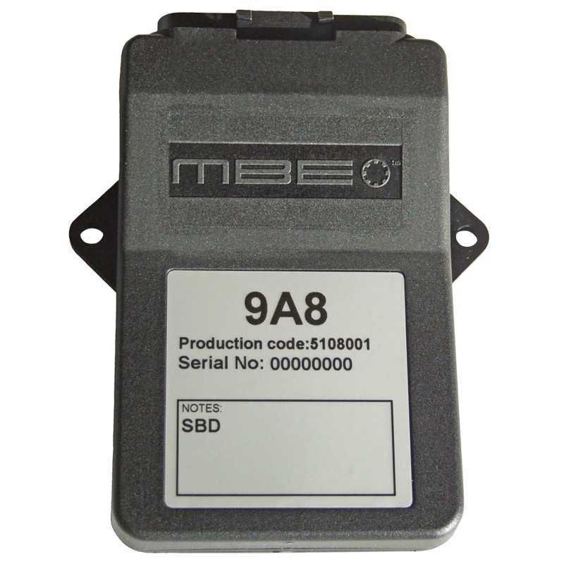
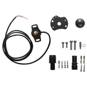
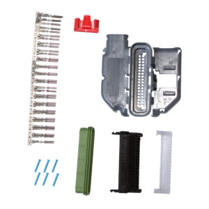
MBE9M8 ECU, Fuel Injection up to 8-cylinders
MRP Without VAT:£819.00
MRP With VAT:£982.80
MBE9A8 ECU, Fuel Injection up to 8-cylinders
993 in stock
Description
MBE9M8 ECU, Fuel Injection up to 8-cylinders
MBE9M8
This ECU is designed for sequential fuelling on engines up to 8 cylinders (high impedance injectors). It can run distributor or distributorless engines up to 4 cylinders. It is generally designed to allow the user to optimize the fuel & ignition settings to get the best out of an engine.
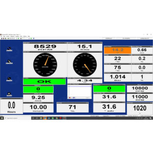
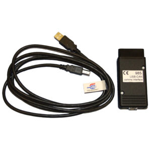
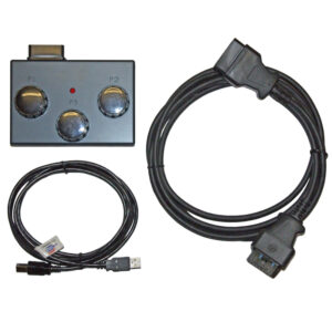
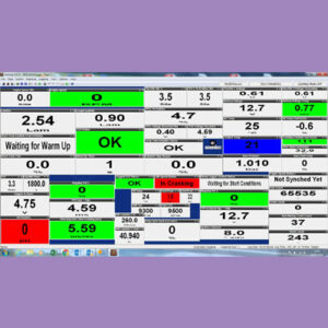
It uses USB communication from your laptop, which is then converted by a small piece of hardware (MBE985) that converts the USB in CAN, which is a more stable system, used by car manufacturers worldwide. You will need our basic CAN mapping kit MBE-MAP-KIT-3-CAN and the necessary adaptor, if you are using one of our harnesses, to read information and/or make changes to the mapping in the ECU.
All our MBE ECUs will be loaded with a base map as close as possible to your requirements. In addition they are capable of being adjusted by the user via a computer. All ECUs are fully tested during manufacture.
Crank Sensor & Trigger Wheel Input
Most manufacturers use inductive type crank sensors. If your engine uses the hall effect type, MBE ECUs can be built to order with this type of input.
MBE write special code to allow the use of a range of different trigger wheels, most commonly 60-2(GM/VW/Bosch), 36-1(Ford), 24-1(Suzuki Hayabusa) & 24-2(Suzuki Hayabusa 2008 & other late Japanese bike engines) to name but a few. The range of trigger wheel patterns is every increasing, so please download Easimap 6 PC Software to check what patterns are currently available. We can supply a range of specialist sensors & suitable trigger wheels for applications that currently have no trigger wheel.
A special piece of software has been written by MBE for Hayabusa and other bike engine set ups called soft start, this was produced due to known problem with the standard starter motors, that if the battery got a bit low sometimes the engine would kick back on starting and engage the starter clutch. This would, if you were lucky only damage the starter clutch itself, but if unlucky could break off part of the engine cases. Without going into too much detail, the ECU allows the engine to get up to speed during cranking before attempting to start the engine, if the engine does not reach sufficient speed it will not allow the engine to start, so damage cannot occur.
Throttle Position Sensor Input
Throttle position sensors are used to inform the ECU of how much load is being applied. The throttle position sensor informs the ECU rate of throttle change to calculate acceleration fuel & when the throttle is closed, this information can be used to enable the ECU to do idle control. They are commonly used on single or multi-throttle body applications. They are also used on turbo engines in some applications.
The throttle position sensor PT1 is the most common type we use on our throttle body kits. Most OE engines have throttle position sensors* as standard, you will be able to configure the MBE to suit. *Some engines have throttle switches, they look identical to throttle position sensors, please check to ensure which type you have as throttle switches will need to be replaced.
Ignition & Coil Input
The MBE9M8 has four ignition drives, that can be fired either sequentially or in wasted spark mode, depending on requirements & set-up. The normal MBE9M8 has built in amplifiers so there is no need for expensive external units. You can use coil on plug, which is four individual coils (such as used on the Suzuki Hayabusa & Duratec engines) or wasted spark coil packs (commonly used on older GM, Peugeot and Ford engines). If your coils have amplifiers built in, such as the Honda K20 coil, the MBE ECU can be specially built to suit this type of coil.
When being used on a 6-cylinder engine, you can use a wasted spark coil pack from many of the production cars e.g. GM. If you are using an 8-cylinder engine, you could use a pair of the 4-cylinder coil packs. NOTE: If you would like to use coil-on-plug on a 6- or 8-cylinder engine you would need to order a special MBE9A8 to run external amplifiers, which would then allow you to run the coils in pairs.
Injector Input
The MBE9M8 has eight sequential fuel drives, which can run up to 8 injectors between 12 – 14 ohms. These can be set-up for a 4 cylinder engine with upper & lower injectors, 6 cylinder engine or 8 cylinder engine. Other options are available, check current ECU software. The ECU has a 16 bit fuel map, which allows ultra fine control. This means you can use very high flow injectors & still obtain very accurate mixture control particularly when setting up for SVA & MOT purposes, which can quite often be a problem with less accurate systems.
Water Temperature Input
The MBE water temperature input circuitry allows the use of 2 different types of sensor, either the MBE/Bosch/Nippon Denso/Lucas water temperature sensors (all use the same calibration) (WTS1) or Ford type which uses a completely different resistor value. This is selectable within the ECU. These 2 types are pre-calibrated in the SBD maps, you can also create your own calibrations if you require.
Air Temperature Input
The standard input circuitry allows the use of MBE/Bosch/Nippon Denso/Lucas air temperature sensors, which all normally use the same calibration. You can also create your own calibrations if you require, different circuitry options can be custom built for additional cost.
Barometric Pressure Input
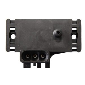
The barometric pressure sensor compensates for atmospheric pressure changes due weather conditions & altitude. The sensor input is 0 – 5V, it is fully calibratable by the end user. The ECU will normally come with calibration for the MBE/GM sensor (car engine) or a specific engine calibration to suit its standard sensors.
Boost/MAP Pressure Input
The boost/MAP pressure sensor compensates for changes in manifold pressure, most commonly used with turbo applications. The sensor input is 0 – 5V, it is fully calibratable by the end user. The ECU will normally come with calibration either for the MBE/GM sensor (car engine) ) or a specific engine calibration to suit its standard sensors. The ECU can make changes to fuelling & ignition according to pressure.
Lambda Sensor Input
The lambda input can be used for either:
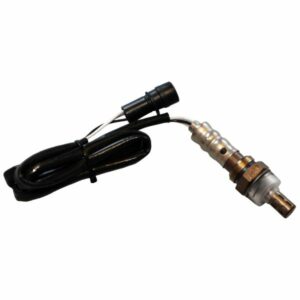
Lambda 1 control using a 3 or 4 wire sensor, allowing the user to set up their engine for MOT or SVA purposes.*
or
With the use of an external wide range lambda system, you would then be able to program the ECU by using a self-learning mode. Lambda targets can be set within the ECU according to speed & load to suit your engine.
*Please note to obtain SVA or MOT test passes you will need use a catalytic convertor. We would recommend the use of a high-flow motorsport cat in order to not compromise the performance of your engine.
Power Shift
Power shift can be configured in various different options, it’s simplest form is a single cut time. With use of ‘complete on target gear’, this allows the ECU to vary the cut time to lengthen or shorten it depending on how long the gear change takes. This time can vary dramatically depending on conditions (requires gear position sensor input). Powershift now has the option to either cut the spark, retard the spark or a combination of the two depending user requirements. There is an option for ‘cut when pin low’, this normally for use with external devices. Also there are many safety features built in, such as, lock out timers & continuous assert to protect against power shift being triggered accidentally.
Fuel Pump Output
The ECU switches on the fuel pump output when 12V ignition is supplied to the ECU for a period of 2 seconds. The output will then switch off until engine speed is measured by the ECU, it will then turn the output back on again until the engine stops. This is a safety feature as in the event of an accident & the fuel line is cut, once the engine stops, the fuel supply will switch off. This is switched negative output & must be used to trigger a relay. Our off the shelf harnesses already have the relays built in.
Shift light & Combined warning systems Output
The shift light output is configurable in several ways, it could be set-up as a simple shift light which is purely rpm dependent. If you have a sequential gearbox & supply the MBE9A8 with gear position, you can have a gear dependent shift light. If you add a low pressure switch or pressure sensor to the MBE, you can set-up a low oil pressure warning, which can also be rpm dependent. This can be configured to trigger an oil light or linked to the shift light, so one output can do 2 functions. We also have designed a bleeper system, which many competition drivers use & find more unmissable.
Programmable Pins
You have a number of programmable pins, which can be selected e.g. fuel pump, water pump control, shift light, etc. Choose the functions you would like to use, then go to the options you have selected in Easimap 6 where you can configure them to suit your requirements.
Tachometer Output
The MBE9M8 ECU produces a square wave 12V output, this is configurable from within the ECU for the number of pulses that occur on the tacho signal per engine cycle. This means it can be programmed to suit your own tachometer’s requirements. The tacho signal also has programmable duty cycle. If you intend on using our MBE9MD display or a dash such as an AIM that can be configured to receive the information over CAN, you would be able to use the tacho output from the MBE for a different function since it would be no longer required.
Idle control Output
The idle control strategy on the MBE9A8 is based on what has been developed for production cars. You can set different target idle speeds according to engine temperature. The ECU adjusts the ignition advance to maintain the target idle speed, according to the parameters set. There are various strategies available from simple idle against engine temperature, idle speed against engine revolution after start, please check the current software from available strategies.
Cam control Output
The MBE9M8 has a single variable cam control output that can be used on engines that have a single variable cam. It can also control VTEC, such as used on the Honda or similar. By using the generic output to control a relay, the VTEC can be switched off & on according to speed, load & other parameters that may be required.
If you require twin variable cam control, you would need to use one of our more advanced ECUs.
Radiator Fan Output
The MBE9M8 is fully programmable, not only can it be programmed to switch off & on at given temperatures but it can even be programmed to run on after the ignition is switched off for a given length of time or until a specified temperature is reached. If you are programming for specified temperature after engine off, you would need to run an electric water pump to ensure water circulation.
Generic Outputs
The generic outputs can be selected as one of the programmable pins, this allows you to use an output to control either an additional piece of equipment or even as a warning indicator. For more information, please download Easimap 6 & go to Generic Outputs.
Electric Water Pump Output
The water pump output can be programmed in 2 different ways:
Firstly with PID control which means it can be programmed to control an electric water using an external amplifier, the speed of the pump would vary according to temperature. This gives very accurate temperature control within your engine.
Alternatively, it can be programmed to switch off & on at given temperatures. It can even be programmed to run on after the ignition is switched off for a given length of time or until a specified temperature is reached.
Both methods can be used in conjunction with rad fan control, so that once the ignition has been turned off, the water pump would keep running until a given temperature or time has been reached.
Turbo Output
The ECU can control the waste gate of a Turbo via PID controller. The target boost pressure can be set within the ECU with different targets according to speed & load. Compensations can be programmed for air temperature, coolant temperature & barometric pressure. Boost can be controlled in either open loop or closed loop. There is also gear dependent boost limits as well as the option for a dash selectable limits.
Anti-lag Output
Anti-lag is available on the MBE9A8 ECU, it can control an air by-pass valve. There are various strategies that are possible, even the option for missed spark, which allows the programmer to reduce the temperature of the exhaust gases by controlling the number of sparks fired while anti-lag is active.
Traction Control Output
The latest design on the MBE9M8 uses the same software as on the MBE9A9 but due to the fact that it only has one wheel speed sensor input, requires the use of a sequential gearbox. The ECU can then calculate speed difference from the gear ratios. There are 7 different maps which can be selected via a rotary switch. Uses the same selector as Launch Control. The software has become so refined that the software only required one slip difference value and this works whether the track conditions are either wet or dry. This makes it easier for the user to set up and ideal for all track conditions. The current software has been developed over many years of in-house testing and has won many championships in rallying, racing, sprinting and hillclimbing.
Launch Control Output
Launch control on the MBE9M8 can be configured to use up to 7 different launch maps. Each map can be set with the different launch rpm & can be externally selected by the user depending on track conditions.
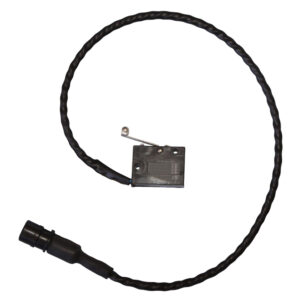
The launch control is activated with a launch switch (fitted to the clutch pedal SWT-MICRO-SL-LL-SS (NC)) & button (NO) either mounted on the dash or steering wheel with a sequence as follows;
1. Depress the clutch (switch triggered only when fully pressed to the floor), which activates launch switch.
2. Then push steering wheel button, which arms launch.
3. Release steering wheel button, launch then becomes active.
4. Depress throttle by desired amount, which will bring the engine rpm to your pre-set launch limiter (according to selected setting).
5. Then release clutch, the ECU then progresses though the launch map maintaining the programmed rev limits, which you have set to increase over a longer or shorter period of time as desired.
Uses the same selector as Traction Control. If traction control is set up within the MBE9M8, the launch control will then switch from launch to traction control automatically, please discuss settings and set up with your engine programmer.
Data Logging/Histograms Output
The MBE9M8 has an inbuilt memory that can record a series of histograms & engine hour clock for recording total engine run time. This will enable the engine builder or programmer to monitor engine life if any misuse of the engine has occurred, such as excessive engine temperature or over-revving. It is also possible to log direct to your laptop from the ECU any information being transmitted by your ECU provided your laptop is connected.
Data Logging/CAN data stream Output
The MBE9M8 has a user configurable CAN data stream, this can be set up to be used with many external data loggers & displays. You would need to contact your data-logger/display manufacturer for the correct protocols.
OBD Scan Tool
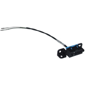
From 9A-Release-be400 software onwards, the option to use an OBD Scan Tool has been added. You will be able to use it to check faults relevant to your ECU as you would do on a normal production car. The scan tool cannot be used for programming of the ECU and an MBE mapping kit is required.
Fault Detection
With 9A-Release-be400 software onwards, component fault detection has been added. The ECU can now detect whether relays, injectors and many other sensors have either become open circuits due to damaged wiring or a fault with the components itself. The ECU will show an instantaneous fault under the ECU status, this fault will also be logged by the ECU and be visible under the ECU logged fault status to show that a fault has occurred until the power supply to the ECU has been disconnected or cleared by the user. This will aid the owner or the mapper in pin pointing faults quickly.
More functions are continuously added to the MBE9M8, please download Easimap 6 for the latest updates.
Related Products
Basic CAN Mapping Kit for MBE CAN based ECUs
SKU: MBE-MAP-KIT-3-CANMRP Without VAT:£160.00
MRP With VAT:£192.00
Micro Switch Sealed For Launch Control
SKU: SWT-MICRO-SL-LL-SSMRP Without VAT:£82.24
MRP With VAT:£98.69
Professional CAN Mapping Kit for MBE CAN ECUs
SKU: MBE-MAP-KIT-4-CANMRP Without VAT:£550.00
MRP With VAT:£660.00
993 in stock

